
Seems like I’ve played with a lot of SABA radios in recent times. I was introduced to them when I was first given one in the early 2000’s by a work colleague back in Germany, where I spent about 8 years of my career. Nice radios, and WAY overbuilt. The SABA ”greencone” drivers enjoy a good reputation among certain european audiophiles who are big into single-driver, wide-range speaker systems. A few months ago I had a SABA come into the shop for general repair – just the radio chassis – and that unit was in pretty good shape except the FM section was dead. A few power supply caps were replaced as well as one very critical cap in the FM oscillator section, plus a full alignment on each band put that unit back in order.

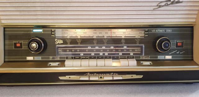
These are lovely radios, made from the mid-50’s to the the later 60’s, and they were good examples of a German cultural tendency for engineering for engineering’s sake. Lots of features like: animation/indicators, flying ferrite antennas, optional remote control (wired) and an approach to designing a radio to out-engineer the competition are all present to be sure. Most recently, I was contacted by a gentleman who inquired if I could support a full restoration effort on a 400. I agreed, and after locating a suitable candidate, a SABA 400 Automatic 10 (export version, going up to 108 MHz) he purchased it. He had to drive out of state (to Wisconsin) to find one that was physically in good shape with just a few mechanical and electronic issues. The chassis was quite clean – very well stored over the years and quite complete in condition save a few minor things. This restoration ran a total of about 25 hours of work to accomplish. Four evenings working with the customer together plus a few evenings on my own were invested. A similar model is seen here:
https://www.radiomuseum.org/r/saba_300_automatic_stereo_11.html
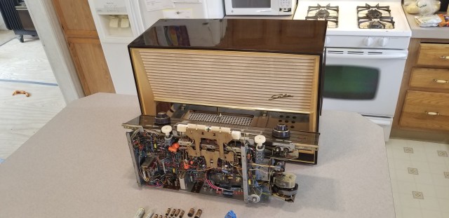
Looking at the radio on the bench for the first time, it was clear that the automatic tuning, arguably the most intriguing part of this type of radio, was not working. The motor looked good – not burned up as some of these typically are. The various radio bands all received at least something, but weakly and they could clearly be improved. All the dial strings were intact, a real relief to me, as the last SABA I worked on had most of them broken, a job that took a couple of really tedious tweezer-and-needlenose hours to rework with new dial cord and some springs. These units are so over-engineered that they are not easy to work on – many things are not out in the open, totally buried or just not easy to get at with tools. On the other hand, from an alignment standpoint, they are very well designed and if you have the original documentation to go by (we did), getting the performance back up to snuff is rather easy. Those adjustment items are out in the clear and really well organized. They also use a 7-pin miniature tube socket to bring out all the relevant test points, which, after making an adapter, really makes the setup easy.

You don’t need an oscilloscope with these to do a full alignment, but you WILL need a bi-directional (zero center) MICROamp meter. No issue, my Fluke benchtop meter has a uA scale and does +and- current.

Getting back to the Automatic, after some discussion we decided to first replace the iffy power supply cap situation that someone had soldered in to keep the radio going. It was a ratty affair, a old-stock 60’s American two- section electrolytic had been cable-tied and taped into place. The poor install and lack of insulating the B+ line was not as much of an issue as the overrating of the unit. It was more than twice the original unit’s ratings in uF, which, while it WILL keep the hum away, also really stresses the rectifiers for the huge surge of current it needs to fill at turn-on, and the 60 Hz peak currents of normal hour-to-hour use are also higher than the power supply was originally designed for. That, and the fact that the original rectifier was a selenium unit, indicates to me whoever worked on this didn’t have a strong background in theory. The only way I could see clear to add that much capacitance would be to upgrade the rectifier to a modern bridge and way over-rate the current in selecting a unit. But none of this improves the radio. The original was already engineered to a high standard, so the only thing to do was rip it out and rewire it back to the factory standard. Since a similar German-style 3-unit multi-section cap with stud mount is hard to source, and we did have some extra room in the area, we went with a large terminal strip that could support 3 individual caps for each section. That will also make future servicing much easier.
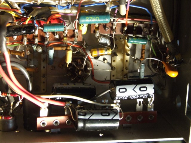
Because they used a 2-section cap, not three, the old repair also had wrongly combined two of the sections, which is a recipe for feedback between the various sections that were supposed to be isolated, power-supply wise. That sorted, I made sure that the isolation transformer and Variac I had set up nailed exactly the 125VAC line voltage under load that the radio voltage selector was set for. We then set about looking at all the voltages around the tube sockets to compare with the factory documentation. The customer had made the wise step of ordering documentation from a gentleman in Belgium. It was all in the original German, but having worked in Germany for about 8 years in automotive engineering, I’m quite fluent and can handle that. Most of what we measured was in tolerance, but some were clearly not. We noted everything down on the schematic and sat back and took a look at what we had.
One thing was clear, something was very wrong in the motor drive circuits – these voltages were so off that I immediately pulled the tube, intending to measure it. It was an ECL80, which is a pentode/triode combination. But what I pulled out was clearly a large-plated dual power rectifier, NOT an ECL80. Someone had just filled the socket with whatever they could. There is not a tube power rectifier present anywhere in this circuit. ECL80’s are not used in a lot of radios, so they are still relatively easy to get and not very expensive, but they are only available as NOS. The customer ordered a few Telefunkens and we moved on with other repairs while we waited for parts.
The power stage in this radio is another example of German over-engineering. Since it was technically a “stereo” unit, meaning you can connect a stereo turntable or tape deck, it has 2 separate power amp stages, each running a class A EL84 pentode. But the radio itself was only a mono circuit, and dual class A is not as efficient as push-pull class AB1, right? Right. So these clever guys decided to go from 2 x 5W stereo to a 12 watt push-pull mono configuration whenever a (mono) radio band is selected up front. So, let’s get this clear. This radio operates stereo class A or mono class AB1 depending on the audio source selected. It switches from two independent output transformers to essentially one big mono output transformer via some complicated switching and cross-wiring of transformer windings. You would never see this on an American radio, if only for the extra costs involved. I love it. It does make the schematic a bit messy to follow, as those front piano key switches are involved all over the place getting things switched over.
The original European EL84 power tubes tested fine on the Hickok 6000A, so we left them in place. We started going though the unit cap-by-cap with the LCR meter, looking for out-of-spec values or leaky high-dissipation caps.
At some point, the customer decided that it was in his scope to just replace all of the aging paper and wax caps. I did that work on a solo-night as it’s a slog and best done in concentration. I stock a lot of orange drops and other high-voltage film caps, so it was just a question of banging them out, one-by-one.
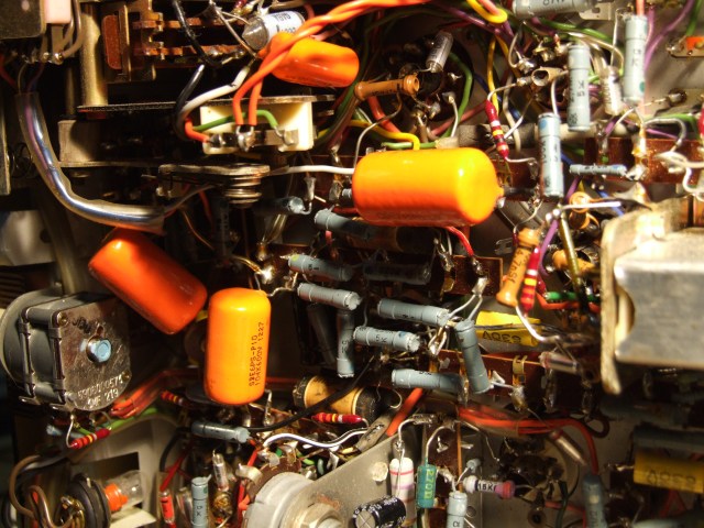
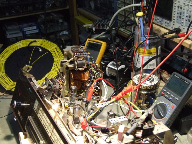
There were a couple really deeply-buried units, and in one case, two special “shielded” three-wire types I could not replace, but everything else came out and was replaced with new. You are probably thinking: “That is going to throw things off a bit alignment-wise…” but that wasn’t going to be an issue, since we had the factory alignment instructions. I finished up the cap work and set up the bench for alignments with the HP8648A RF generator. I use a radial AM coil (yellow) I made for radiated adjustments, and the factory-spec’d coupling and artificial antenna circuits were soldered up to do the conducted tests.
These are specific cap-resistor combinations on 4mm banana plugs, which are connected to the female antenna jacks on the rear of the radio. The radio uses a 460 kHz IF frequency, so that alignment is done first. That sets the fundamental sensitivity of the radio overall. Once that is done, the local oscillators for the LongWave, MediumWave and ShortWave bands are individually adjusted for equal strength across the high and low ends of each band, as well as the frequency accuracy, which is set so that the dial lines up perfectly with each of the number markings at all points for each band. Something was a little off with two of the oscillators, because the shortwave and mediumwave oscillators did not peak out quite the way the instructions indicated they should – it felt like the coils for those two were not resonating or perhaps open. We dug into this (none were open) and then analyzed the schematic to see what was common to both affected bands. We later localized it to a single cap deeply buried under the switch bank sheetmetal that was a important bypass for all of the AM oscillators. One end was flying free. It wasn’t clear to me if perhaps I had un-soldered it to measure or if it had been that way all along – hard to say but there were other components in that immediate area that someone had soldered on since factory. Either way, it needed to be put back in-circuit. Trouble was figuring out which of many possible tie-points it went to. There were dozens nearby on the bottom of the switch bank, all un-labelled. After reading the prints and testing a few things, it became apparent where it was supposed to go. Once that was tacked back down, the oscillator coils were immediately responsive, so we knew we had nailed it.
That misplaced rectifier tube had done some damage. It didn’t take long to notice that it had burned up a couple of resistors, which were duly identified on the schematic for value, and then replaced.
There is a link to this radio series on radiomuseum.org that has an excellent write-up on the theory of the self-tuning mechanism, in German, and I printed that out and studied it for many hours, and later I even translated it into English to be sure I had understood all the details correctly. It can be found here:
https://www.radiomuseum.org/forum/reparaturmanahmen_zur_saba_automatic_steuerung.html
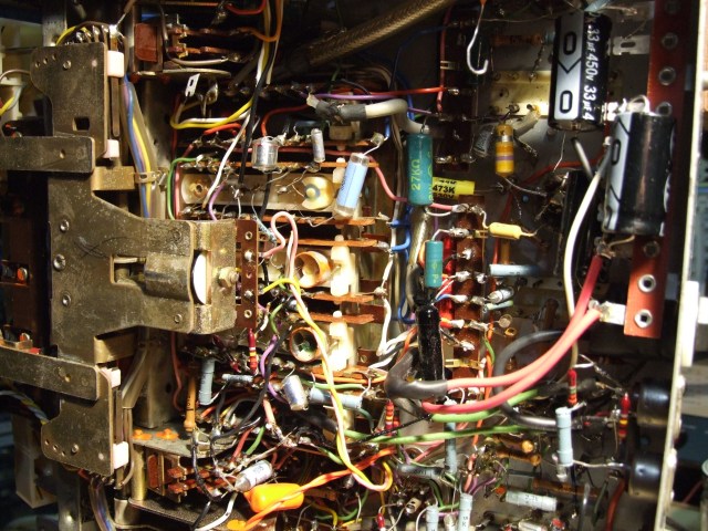
I won’t go into it in great detail here, but it’s essentially an extra discriminator circuit (and gets aligned like one) driven by either the AM IF (460 kHz) or the FM IF (10.7 MHz) that drives a special AC motor with dual pairs of windings set in opposition. There is normally AC over all four of the windings, so the net forces all balance and the armature does not move. When the discriminator is either side of the IF (both the 460kHz and the 10.7MHz feed it in tuned circuits), a phase difference develops that allows a small 60-Hz signal, specially coupled in from the power transformer, to be amplified and driven into one or the other of the motor winding pairs, but which one depends on the phase imbalance being above or below the target frequency. It’s a beautiful bit of engineering considering it was accomplished with tubes and analog signals, and once setup to spec it works pretty darn good. It looks like a ghost hand on the tuning dial.
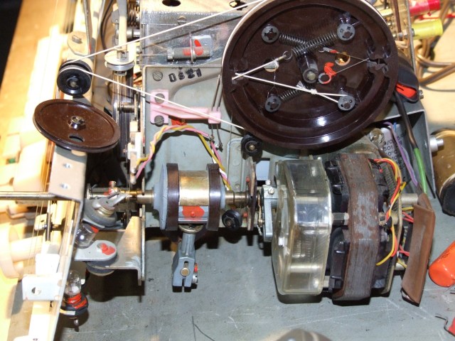
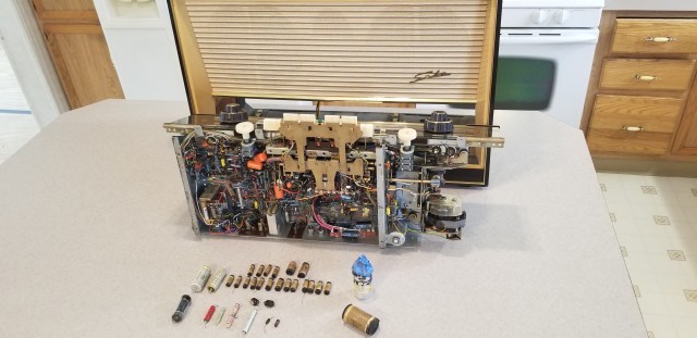
In the picture above, you can see the typical clutch shaft (brown-brass-brown cylinder in the middle) which shuttles the tuning motion from the AM to the FM sections depending which band key is pressed. To the right is the tuning motor, acting on the same tuning shaft. Under the clear cover is the gear reduction. If you look carefully you might notice the whole section sits on rubber isolators. There is factory red threadlocker all over this radio to keep adjustable things nailed down. I stock the original red material from Germany, known as “Schraubensicherungslack” for reasons like this.
Once the tubes came in, we just had to place it and see if every thing auto-tuned as expected – we pretty much figured it would, as I had borrowed a tube from another German radio in my collection to do the control system alignment with while we waited for the new one to arrive. The German document stressed that a really good tube was necessary for the circuit to work well, and our new old-stock Telefunken tube did not disappoint. I could not tune a station any more perfectly centered than the automatic system did, as confirmed by the onboard magic eye tuning meter. I guess we nailed it.
Here’s some video of this rare circuit in action:
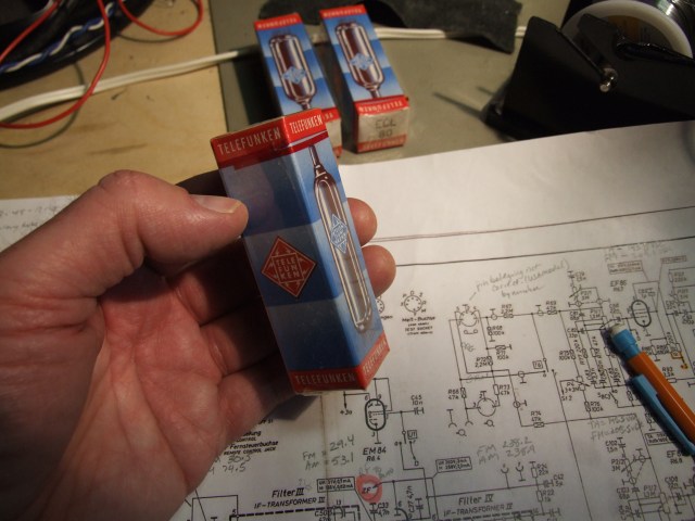
Above: The new Telefunken driver tube required for the auto-tune circuit.
Below: More video of the unit in action, showing what the user sees: the “Magic Eye” being tuned perfectly, and the dial know and pointer moving on it’s own. Remember, this is in 1957!
I was a little sad to see this unit go home – after so many hours you kind of get attached, but every project has it’s end. I learned a lot, as this was the first automatic tuning unit I’d seen first-hand. This radio should provide years and years of fine service to it’s new owner, and sound really good doing it. To that end I added a stereo 1/4″ TRS jack on an unused chassis hole in the back – to allow the connection of a Bluetooth adapter or a simple stereo cable to connect to an audio device. We had to punch a circular hole in the back board to allow access, which the owner was okay with.

Most folks in the US don’t have access to DIN to RCA adapters, they (DIN inputs) were never popular audio connectors on this side of the pond. All said, this was one REALLY fun project!!
-Dan
Epilogue:
I later received the following comments and pictures from the radio’s owner, and thought it would be fun to include that material here as well. This is one smart-looking radio.
Dear Dan,
I just want to drop you a note about my experience at your shop, MyTubeAudio. I am so grateful to have found your place, as without your expertise, knowledge, and experience my Saba 400 would be just a memory. Now it’s going to be a family heirloom. I was glad to have front row seat watching you do your magic on each and every section of the radio. Replacing capacitors and resistors, setting the alignments of AM and FM waves, it was a sight to behold.
I remember how overjoyed I was when you powered it up a got a heartbeat out of her! The sound was wonderful, the automatic motor tuning was amazing to watch, and the length of the dial was full of stations! I couldn’t be more pleased with your efforts on the Saba radio! Thanks so much for making this possible Dan. I had a great time at your shop.
Gratefully yours,
Tim V.


Tags:
SABA, Automatic 400, Autotuning, Stereo 10/T, German Radio, Luxury Radio, German Hi Fi, Radio Restoration, Radio Repair, Old German Radios, Radio Cap Job, ECL80, Self-tuning

Hi Dan,
I have a SABA stereo 400 that I restored about 5 years ago and it ran fine until today and that was just a push button lamp. You are so right, they are over built but really great sets! Long ago I did have to do the AM dial cord and yes that is not fun. Also had a bunch of replacement caps like one of your pictures. If you did one of these in 25 hours that’s amazing!
Dave