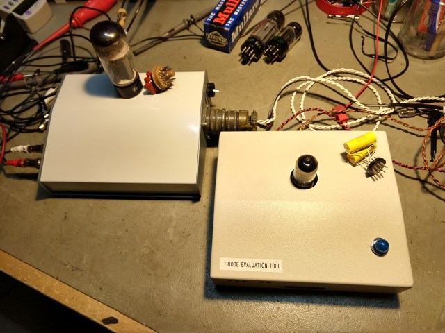
PET: The Pentode Evaluation Tool
It’s been a few months since my post regarding a Triode Evaluaton Tool – the TET machine – where I measured the frequency response of common 12AX7 types to see if one or another really had “more pronounced highs”, “ballsy bass” or “strident mids” or anything similar. If you read that post, you already know that I found less than 0.5 dB variability in the frequency response of small triodes, when ran clean and linear under controlled class A conditions. At the end of that article I mentioned that I wanted to circle back and do the same thing with pentodes. Thanks to the extra time the corona virus has given me (not having caught it, but being forced to cancel my amp appointments for the time being to avoid it) I’ve now had the opportunity to make good on that promise. Here’s what happened.
Class A Pentodes
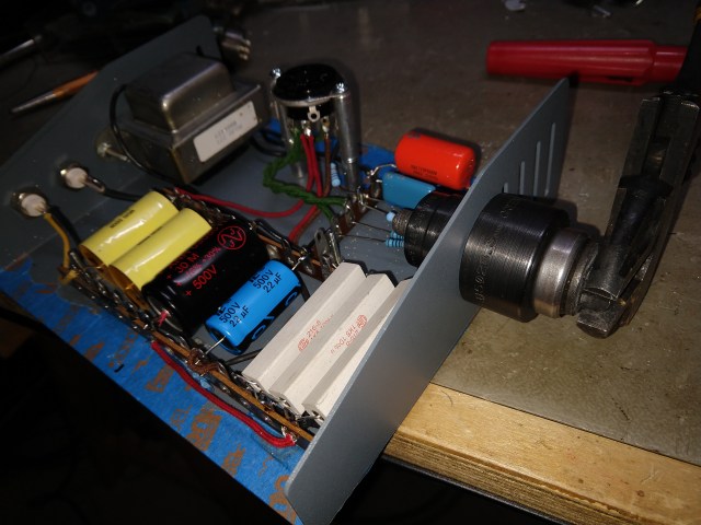
So, given a class A power amp circuit as used in countless pieces of tube gear as a starting point, I set about removing the major sources of non-linearity: the output transformer and the small coupling caps. Using a regulated external power supply and extra filtering, I built the circuit with 4.5k/30W of resistive load to represent the output transformer’s net impedance, losing the inductance and reflected speaker impedance. This is a value that is a compromise, in between what EL34’s and 6L6’s require. I then used oversized coupling capacitors to push the low end of the RC time constant as far towards DC as I could, given the practical constraints of the housing I had on hand.
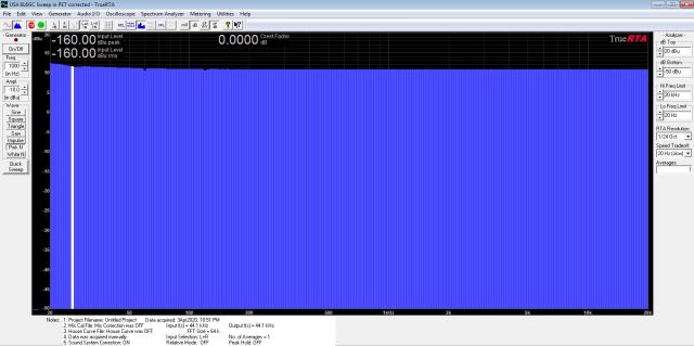
So, we now have a class A amp with a large 1.5uF/630V capacitor coupling the input signal to the grid (compared to the more typical 0.47uF or even 0.1 uF) and on the output side there is total of 2uF/630V coupling the output signal off of the plate side of the 4.5k dummy load. I was a little concerned about inductance, as the loads I used were sand resistors made with resistance wire, so there IS a little inductance there, (about 92 uH each x 3 series resistors, each being 1.5k/10W), but at these frequencies I wasn’t expecting it to be a big problem, and in either case it would also be present during the calibration of the fixture, so that error, if present, should disappear in the cal. As it turned out, in the pre-calibrated state, I did see some roll-off above 10kHz, but it calibrated out nicely in the TrueRTA program.
A Cheap Plug For the Product
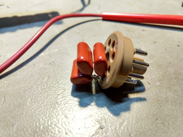
The capacitor/tube base combo I used for calibrating the “thru” path of the fixture has a total of 2uF/630V connecting the grid pin to the plate pin. This means that once I calibrate the fixture, I have the effects of the complete audio circuit path removed from the measurement, and all I should see when a tube is tested is the difference the tube itself makes. It appears to work out nicely.
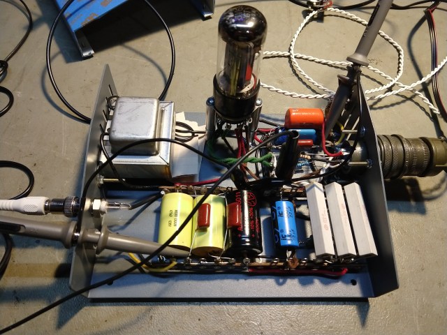
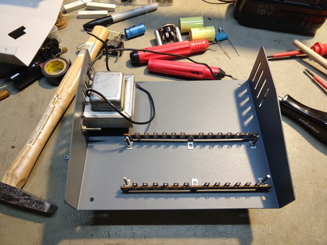
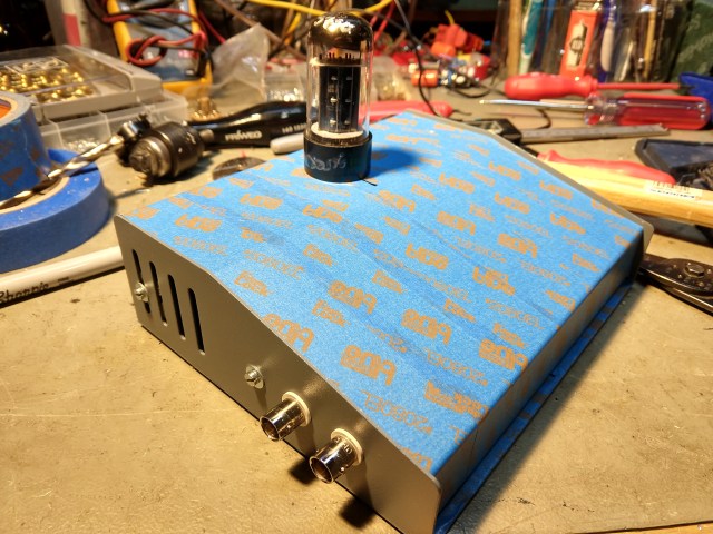
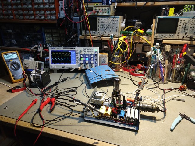
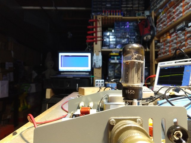
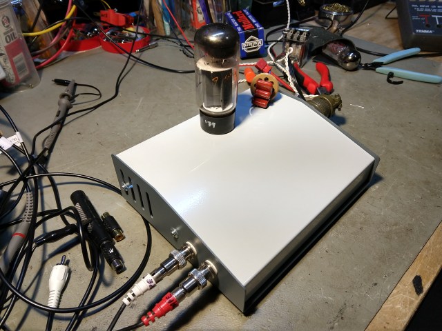
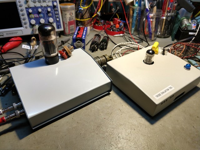
The PET fixture during initial power-up
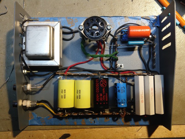
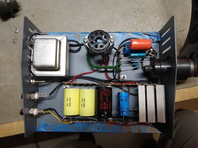
What appears to be a transformer is actually just a very large choke, part of the Pi filter feeding the B+ and the derived screen voltage. Keeping in mind that my B+ is already filtered and regulated externally, this was overkill, but I now have the residual 60 Hz in the B+ supply suppressed to around 90 dB below the signal, so I think it was a good idea. There is an additional 74uF of filtering distributed around the inductor – 22uF at the B+ before the choke, then another 30uF after the choke, and another 22uF on the screen tap of the B+ after the screen dropping resistors. The filtering is based on that recommended by the RCA receiving tube manual for this kind of circuit.
The Plot Thickens…
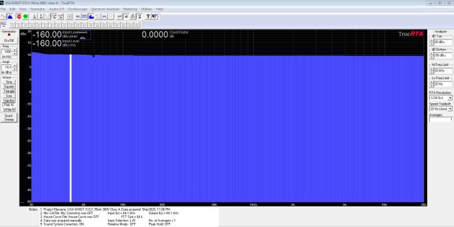
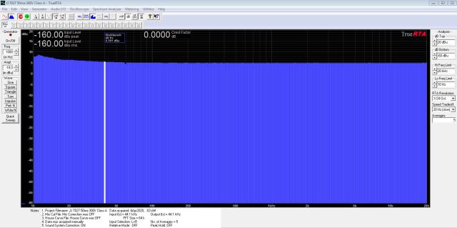
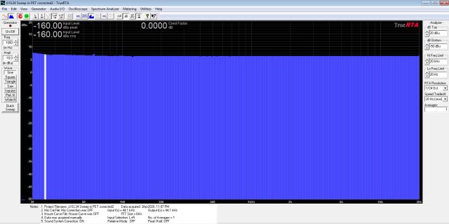
Plot of the GE/Sylvania-type USA-made 6L6GC’s frequency response, in Class A, Vp=300V, with 50ma of idle current:
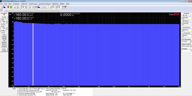
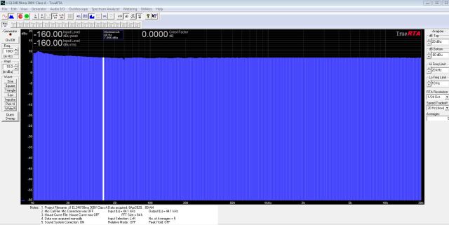
Plot of the JJ Brand EL34’s frequency response, in Class A, Vp=300V, with 50ma of idle current:
The dummy plug with 2uF of coupling capacitors on board.
(OK, it’s only 1.5uF when the pic was made. I later added another 0.47uF when I saw that little bump below 40 Hz in the plots)
The Improvised Build Process
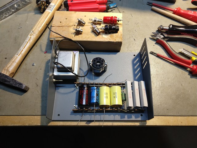
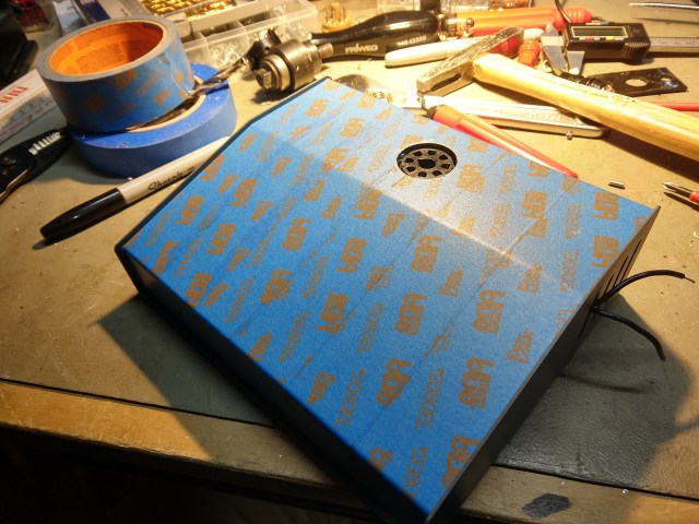
I like Blue Tape. Lots of Blue Tape to Protect Things.


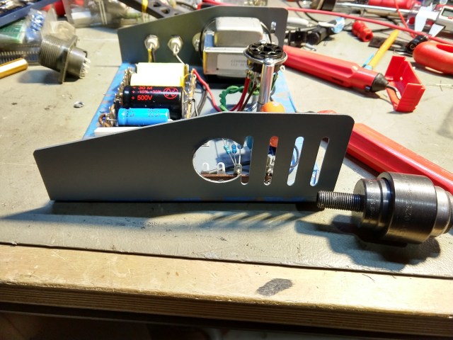
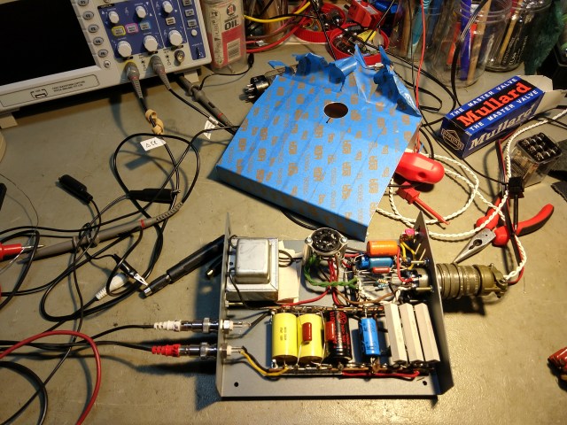
As I did for the TET project, I included a shorting switch to allow me to ground out the input signal (just before the bias feed, and ahead of the input coupling cap) so I can evaluate the noise signatures of these kinds of tubes. I’ve not looked into this yet but hope to soon.
Conclusion
Well, as I suspected, these tubes are very, very linear. For my dollar, if I’m trying to change the tone of an amp (clean tones, we are not discussing an overdriven power stage that’s a different bird, and for that matter, much too loud to stand next to) I’m not going to change tube types and expect to hear any significant difference. Won’t happen.
When it comes to flat frequency response, these tubes are flat within 0.5dB from about 40 Hz to 20kHz. Go look at those plots again at the top. Below 40 Hz I’m seeing a rise of up to maybe 1.8 dB by 20 Hz, but even that’s not much. I have not yet proven if it’s the fixture, the calibration plug, or really the tubes themselves. And both tube types show it, so it’s consistent. So, for all practical purposes the tubes I’ve tested are flat. Way flatter than anything else in the signal chain. Draw your own conclusions about tubes and marketing.
When you think about it, this should come as no surprise. After all, all those really expensive tube hi-fi power amps out there with great specs – they never have any EQ in them, do they? This is because when you do everything else right, tubes will have a flat response and so will the amp. It’s the circuit, not the tube, that sets frequency response first and foremost.
The speaker, the coupling caps, those tone stack slope resistors, and perhaps the output transformer all are going to contribute WAY more than shifting from EL34 to 6L6 tubes or vice versa. The real differences in “American vs British” amps, played relatively clean, are not in their choice of power tube types, folks. They are chosen for power handling and hopefully, reliability in that particular circuit. It’s the L’s and C’s, which each have that pesky f term in their formulas, that alter frequency response. The tubes I’ve tested here are both rather flat. I’ll report back with some more results in the future – I want to test more tubes, more types and look at noise and gain differences, all of which this fixture can illuminate for me. Mythbusting? Seems like it to me. Thanks, Corona!!
Update, 4/6/2020
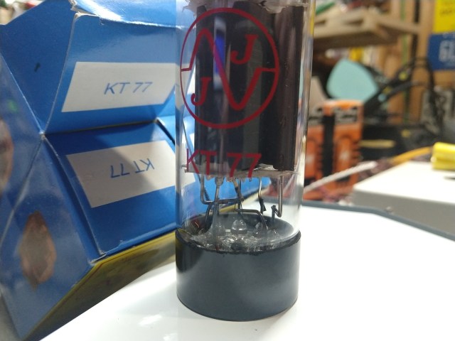
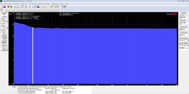
Last night I spent some quality time with the PET and rounded up several examples of power tubes with compatible pin-outs, giving them each a spin. I made screenshots and a picture for most of these tubes during the test. I tested EL34B, EL34II and KT77 from JJ, TAD EL34 and 6L6’s and 7027’s from JJ, all from new matched sets I have currently in stock. In short, there were differences in gain, but not at all in frequency response. Again, the takeaway here is that these tubes all have the same amount of bass, mid, treble and everything in-between. All easily flat within less than 1 dB within the 40Hz-20kHz bandwidth. Below that, the response for all tubes goes up by +1 to +1.4dB as you approach 25 Hz, which I currently think is a function of my dummy plug, the sound card or the fixture. I will investigate this at a later date. I played a fair bit with optimizing the signal levels going into and out of the fixture, and experimented with various plate voltages between 300 and 400 volts, and tried different bias levels. The sound card I am using is definitely not high-end, a Lexicon Omega, but with the right settings I can see a mid-band noise floor as low as -100db.
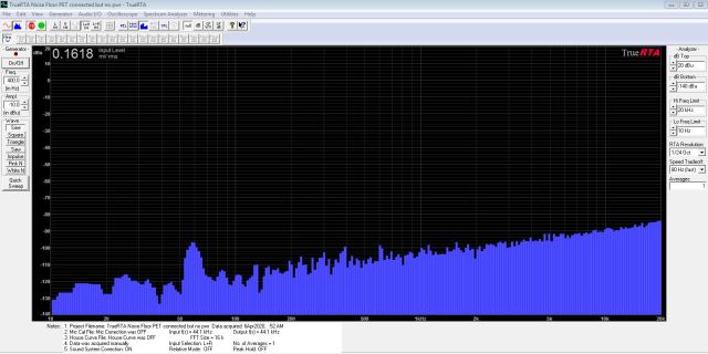
As to residual hum, I’m seeing more than I like, around -80dB to -90dB, even without power supplies being plugged in, and I’ve isolated most of this to the audio cable feeding the input of the sound card. I’ve ordered some new cables to see if I can improve on that.
Here are some of the pics and screenshots. Take note that some of the analyzer settings are much more zoomed-in than others, so not all the screen shots are the same scale. The slight ripple in a few zoomed-in ones appears to be a cal artifact, because it’s present sometimes and not others. I hope to run the PET and TET fixtures over an Audio Precision system soon to verify the accuracy of the plots.