Modern manufacturing realities mean assembly time must be reduced if you want to make a profit. Easy math. Labor is expensive, anywhere you go. The cost of raw PCB’s is pretty much a fixed commodity. Same with most electronic components. Competition in the marketplace means those are costs are relatively low to begin with (in quantity) but still, fixed. The only places you can really find to save money is on the cabinet, grade of PCB and assembly costs. That means choices are made when a target market gets a new amp model. Features vs. price.
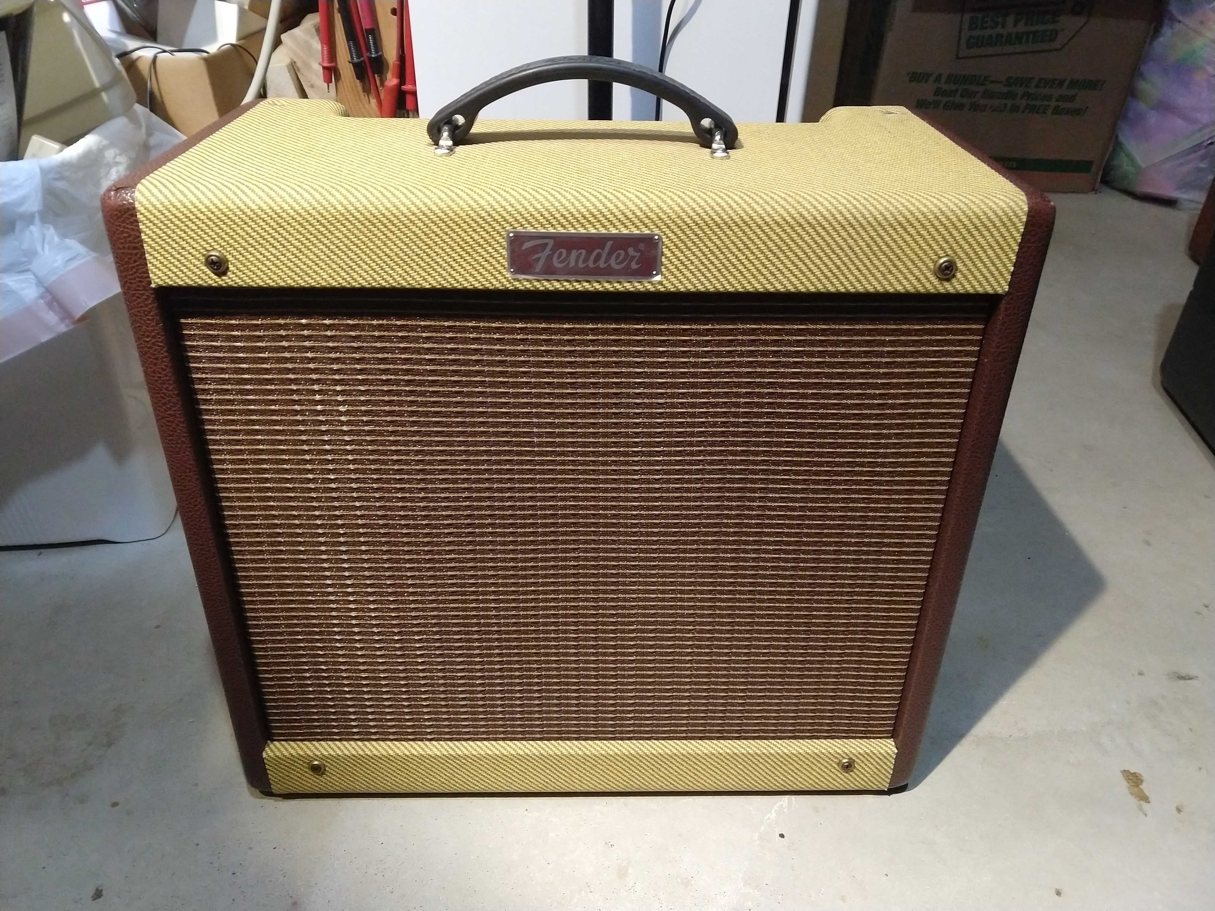
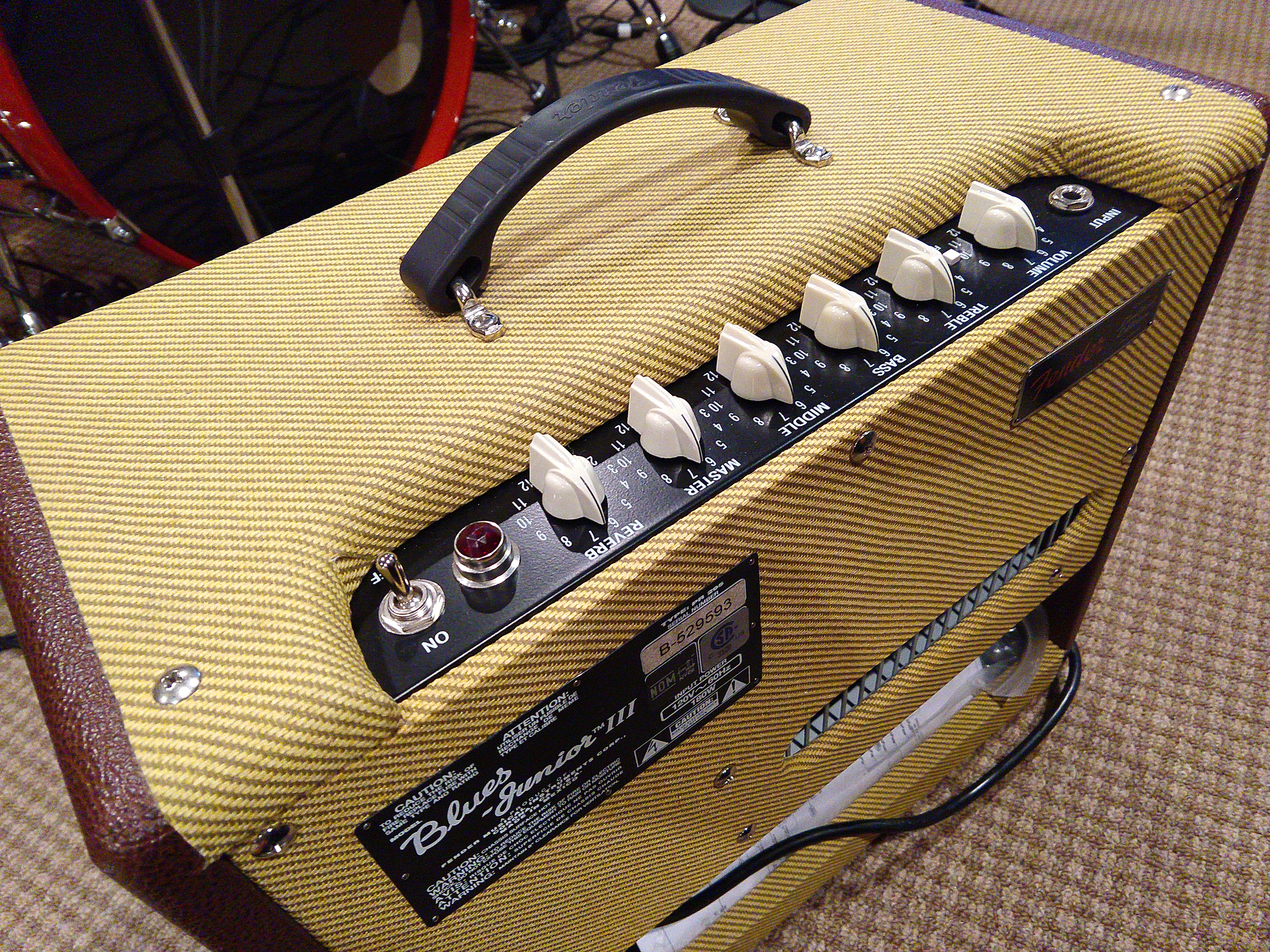
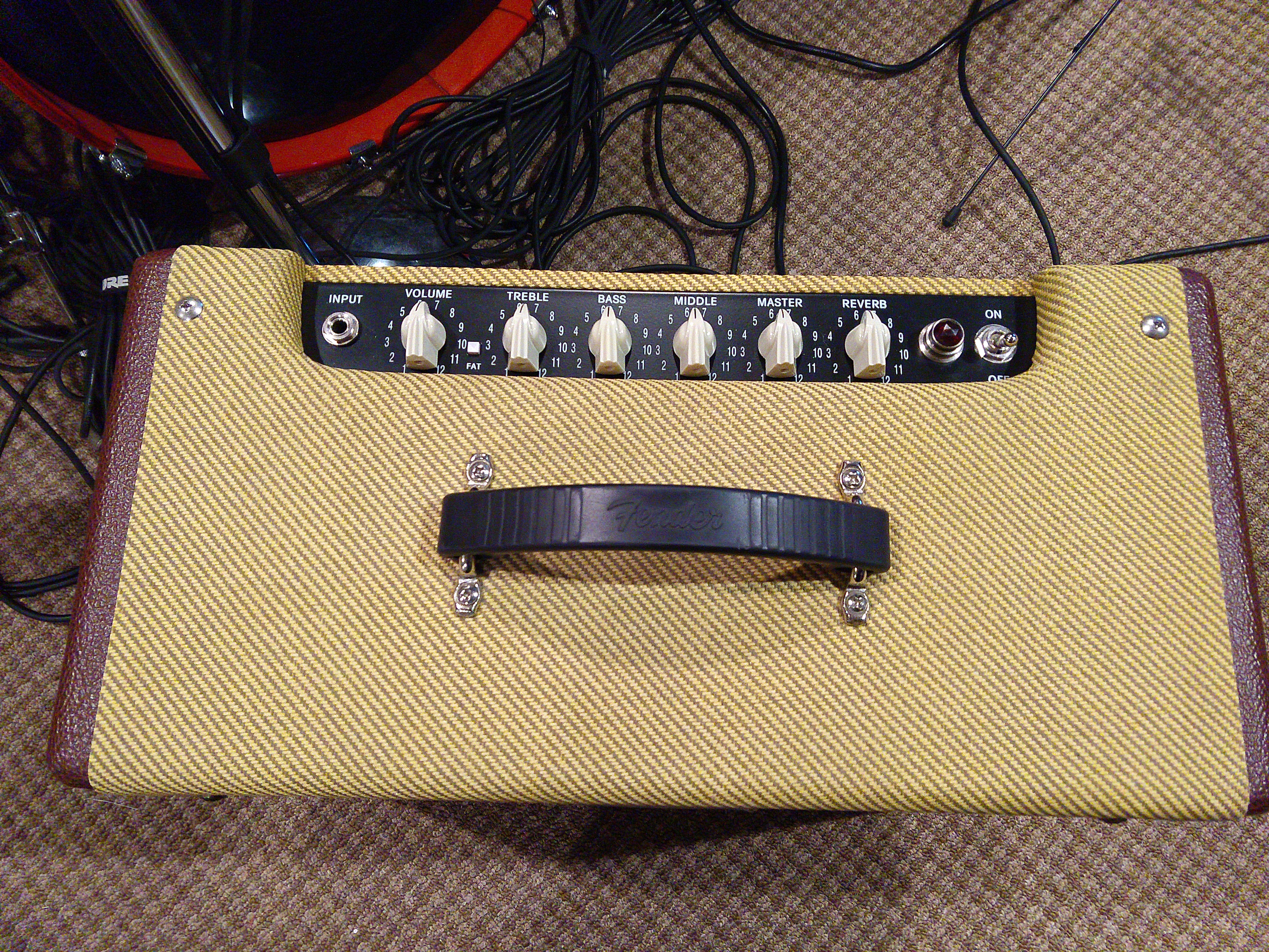
I have many customers that use the popular Fender Blues Junior, and for the money they are a good-sounding circuit, with one immovable caveat. That is cabinet size. The distance (as the gnat flies) from the back of the speaker cone to the front is pretty short, so no matter how a speaker in that situation tries to pump air, at some low frequency the pressure wave will simply cancel itself out. I mean, that when the cone pulls inward to the basket, a positive wave of air pressure develops, while out front, a rarefaction or negative pressure wave is developed. So long as these two are kept separate, we can efficiently make a sound wave that travels effectively into the room where all this is happening – your gig, your garage, your studio. But as that path from back to front decreases, the cancellation frequency goes up – meaning less and less bass gets into the room, even though the speaker might be doing a fine, efficient job of reproducing it. Bottom line, open-back cabinets that are smallish have lousy low-end response no matter what. It’s physics and it does not like to argue the matter. But portability is important, and larger cabinets also take more materials (wood, paint, tolex) to make. So the dollar dictates the cabinet size as well. To get around this, you can simply close-mic such a driver, and capture all the speaker is doing, but that’s only convenient when you have a full PA and everyone is listening to the guitar amp over the mains. Not always the case, especially for weekend warrior musicians. All this to say that a single driver in a small cabinet has some limitations.
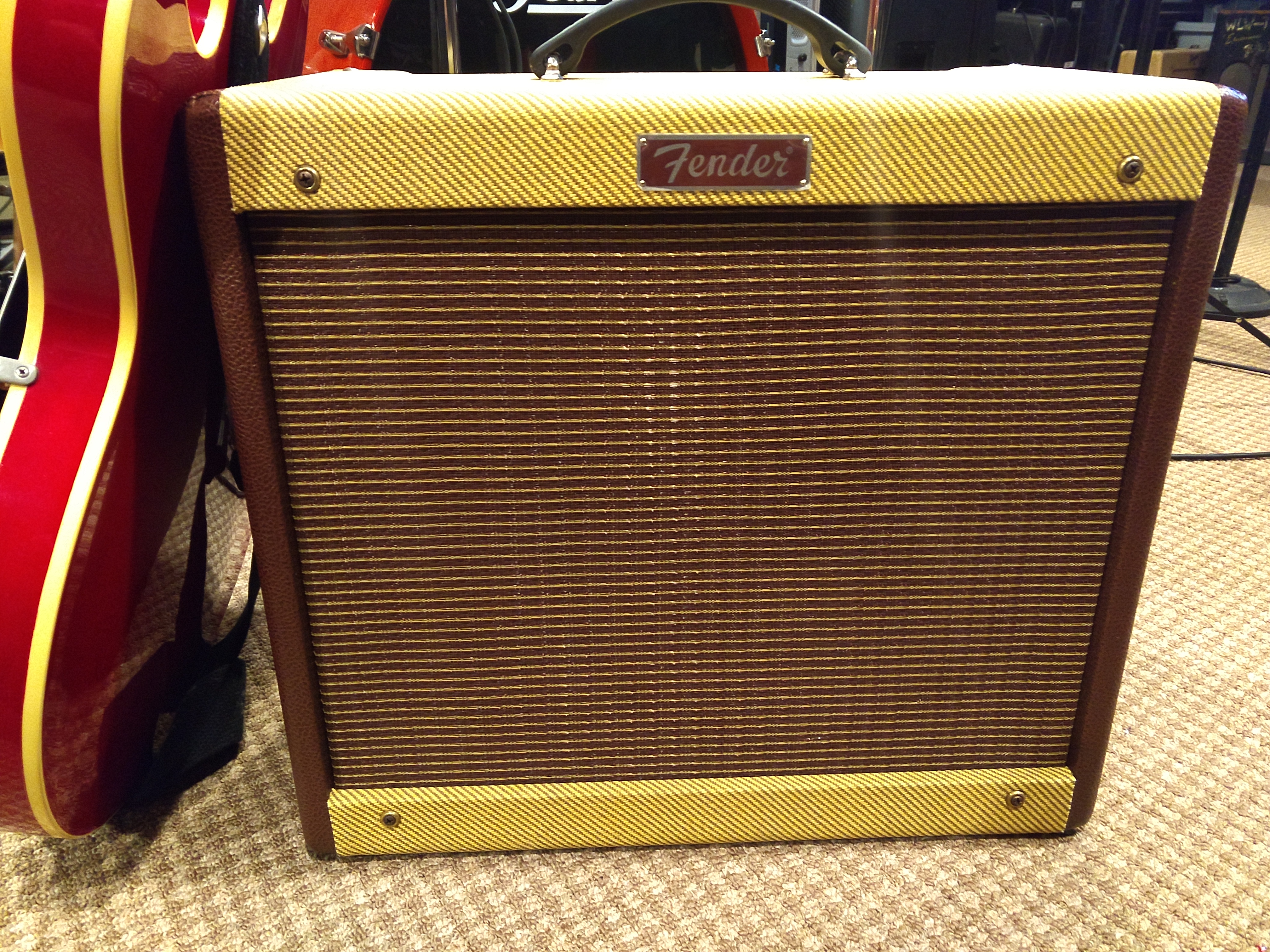
But if you can live with that, the Blues Junior and the Peavey Classic 30 are great sounding amps because they do a nice job of having both an acceptable distortion tone and a very good clean tone in one package. We all know that. Next up on the wish-list is reliability. And this is where manufacturing cost-cutting has helped fuel the industry impression that PCB-based amps can be unreliable. The rest of this post is all about why, and how that can actually be improved, significantly.
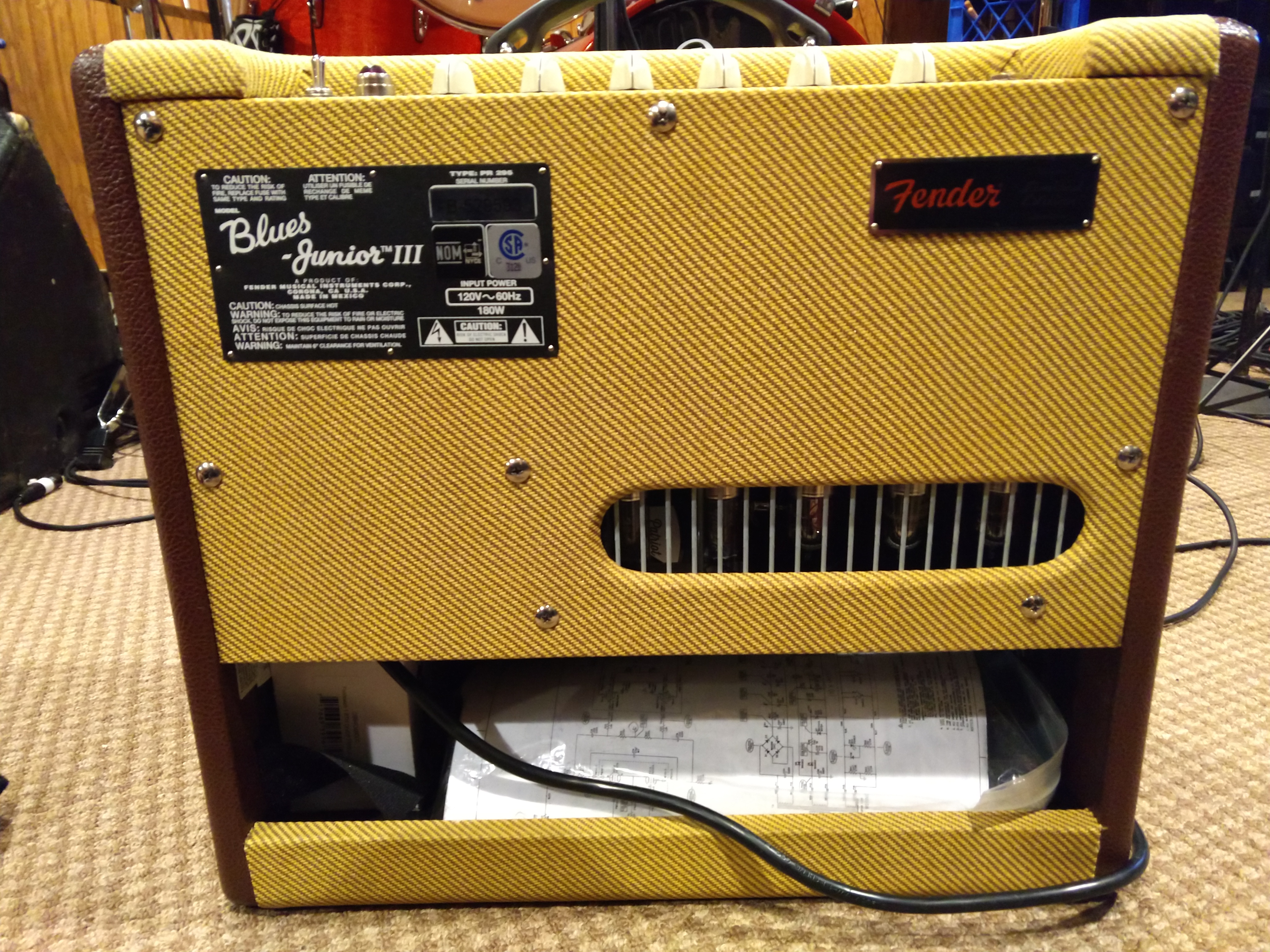
I had an actively-gigging customer with a BJiii that had suffered some failures in the traces around the power tube sockets. I repaired the tracks best I could, but the writing was on the wall. More tracks failed as the amp was gigged, and several months later, it was back on my bench with more cracked traces around the power tube sockets. The customer liked the amp, but as we worked on it, he began to express doubts if he really wanted to keep going down this road. He said that he was torn between selling it and keeping it, as the repair costs were killing the joy. It’s a good-looking version, in two-tone tolex, and I let myself say I was willing to buy it if the price was right, as-is and I would eat the evening’s repair work cost. Deal.
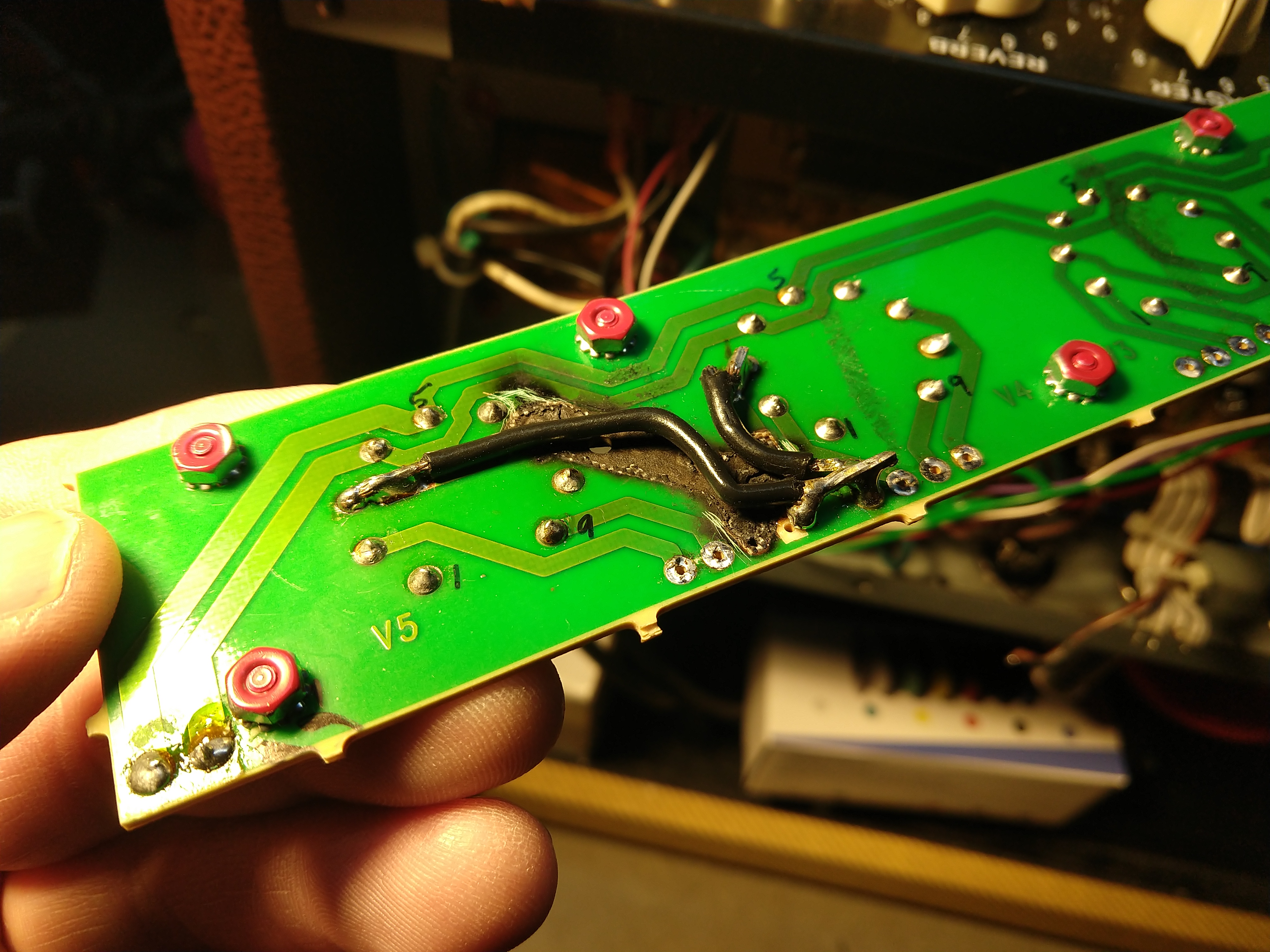
The reasons amps like this have reliability issues is really down to one thing – vibration and the dreaded Single-Sided Printed Circuit Board. For a small-lightweight circuit that lives in a vibration-free environment, the SSPCB is fine and lives a good long life if well-engineered. That means making sure to allow for wide traces and large component solder pads, because the copper traces are essentially only glued to the board. This is really important around those component holes, which take a lot of vibration and stress on large components like tube sockets, caps and transformers. You also need to use a healthy 1-ounce or thicker copper plating (trace thickness) and use physical fasteners for anything attached to the SSPCB that has mass, like adhesive or zip-ties.
In the guitar amp world, all these items are sometimes dismissed for cost-cutting reasons. Double-sided thick copper PCBs with “plated-though holes” are a bit more expensive per square inch, and so an easy way to cut costs, but they have a distinct durability advantage that the through-holes for the components are plated-through, meaning they have a metallic sleeve that mechanically bonds the top and bottom traces together like a rivet, and allows the flowing solder wave to wick up and adhere to both sides of the component lead, top and bottom.
When cut into a cross-section (yes, they can do that for quality control reasons) you can then see a nice rivet-like construction of solder – with a “hershey kiss” cone of solder on each side of the board. This is reliability writ large. The pad area around the component lead has been more than doubled, increasing strength against lifting, making re-work a lot less risky and vibration tolerance has skyrocketed. Also that inner-sleeve isn’t going anywhere, and the whole shebang is a lot more resistant to solder cracks over time. This is partly due to thermal mass, and party due to mechanical strength.
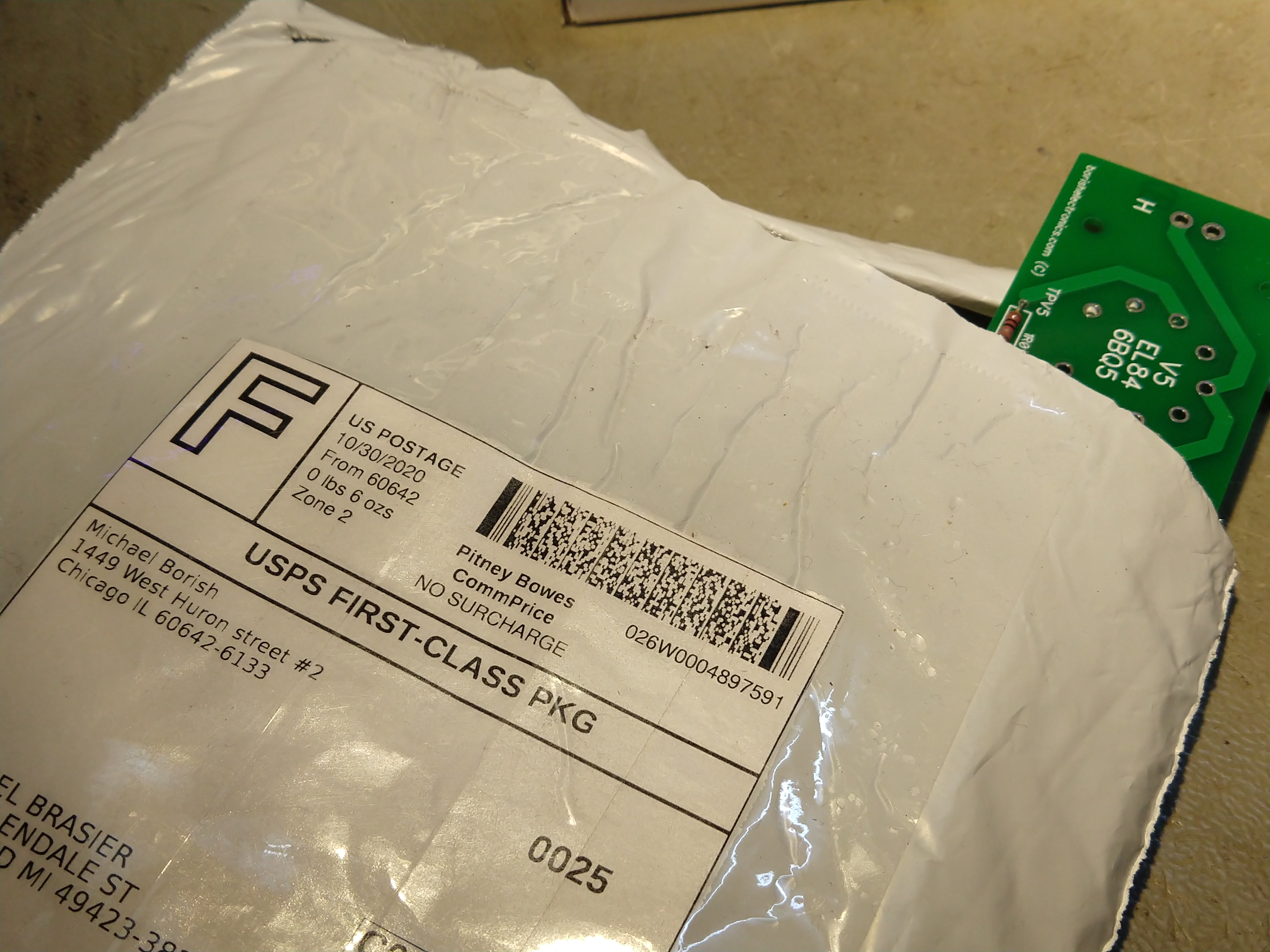
You really give up a lot when you choose to use a SSPCB, but if you are making a LOT of amps, you will see a significant reduction in PCB cost and the amount of solder consumed making each assembly. Now let’s see what can be done about this. I had actually started the measurements and layout for a new identical PCB for the Blues Junior, but shortly into that process I happened to search online to see if it had already been done by someone. It had. Boards ordered. I think they were something like $20 each and I ordered extra.
Source: https://borishelectronics.com/products/fender-blues-junior-jr-tube-board
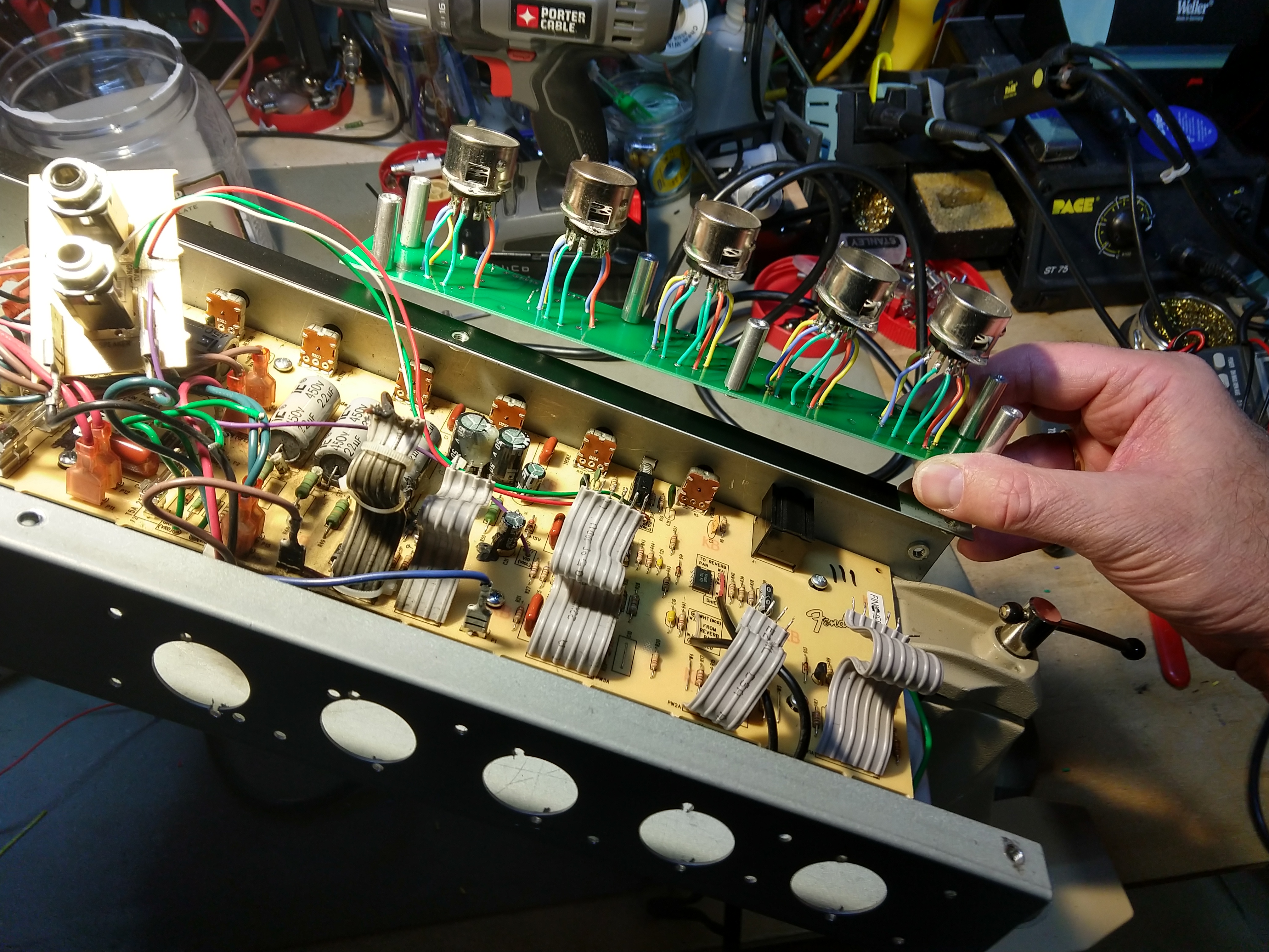
That saved me a ton of time, so well-worth it. The rest of this is best told in pictures, but I will add that while doing this reliability upgrade, it made sense to lose the cheap plastic input jack, provide a means to check bias and do an external bias pot mod do an the amp while at it. These amps don’t have a bias pot, so this makes long-term ownership much more convenient.
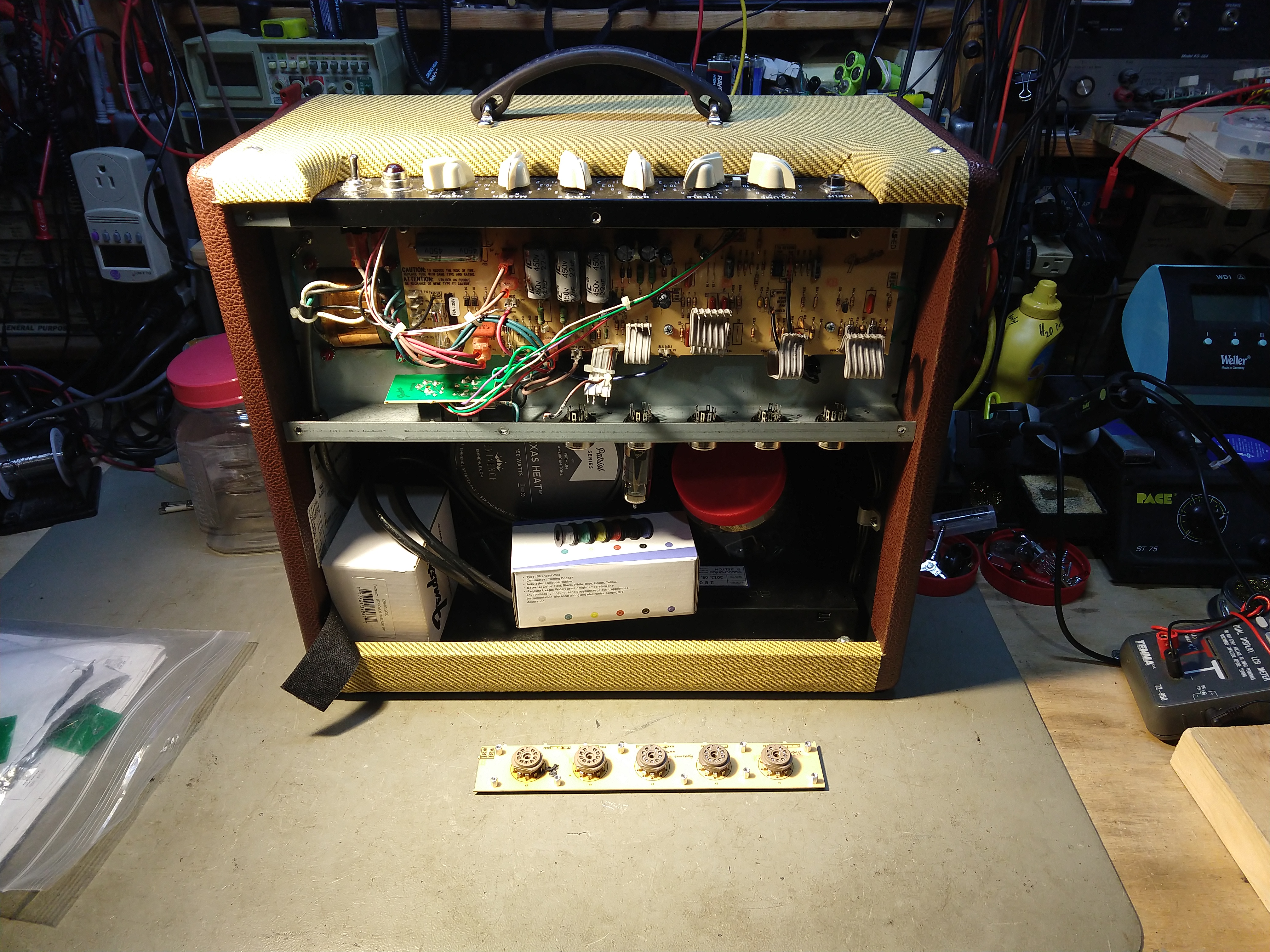
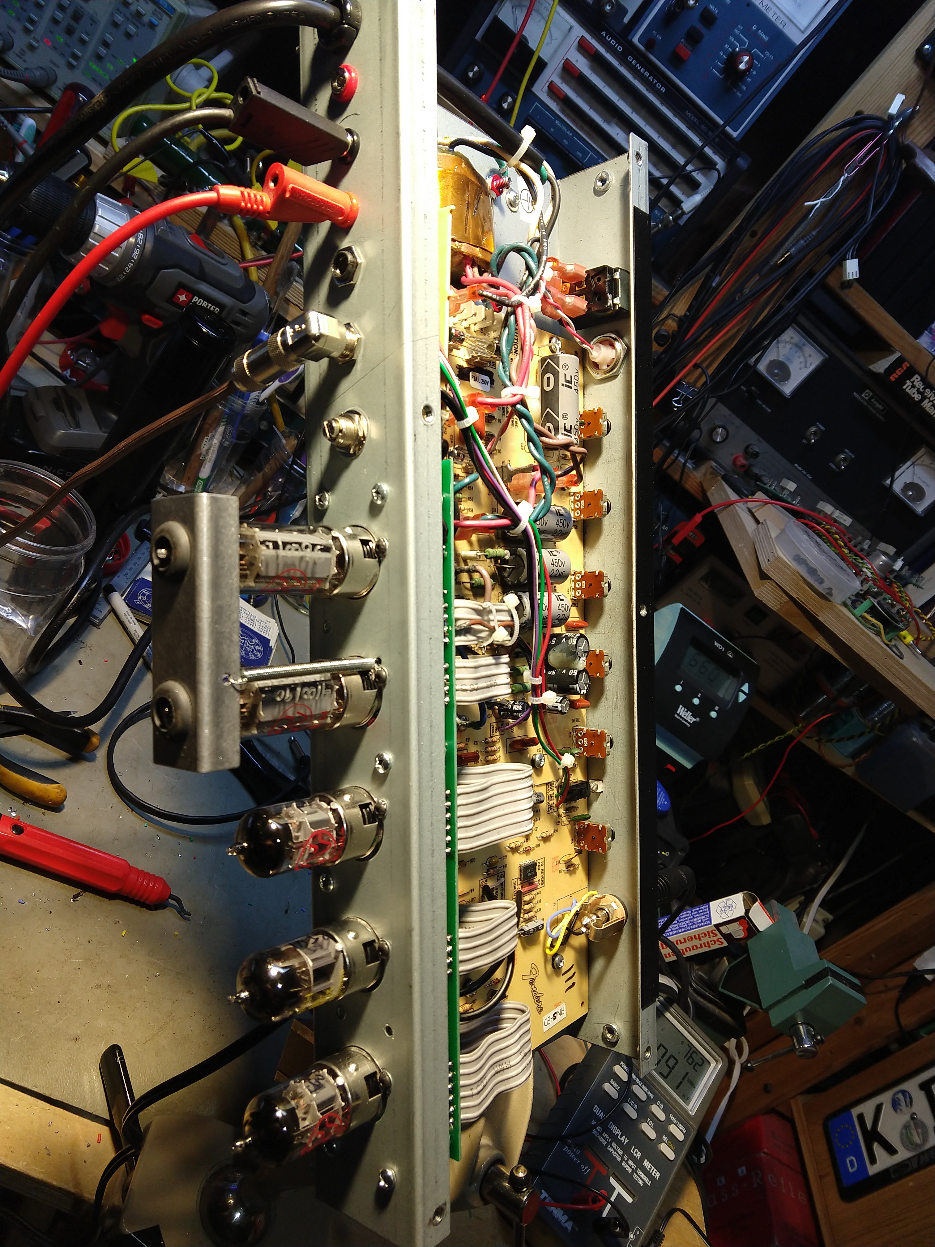
Note the inexpensive Amazon silicone-wire dispenser in the upper left. High-temp wire is easier to deal with.
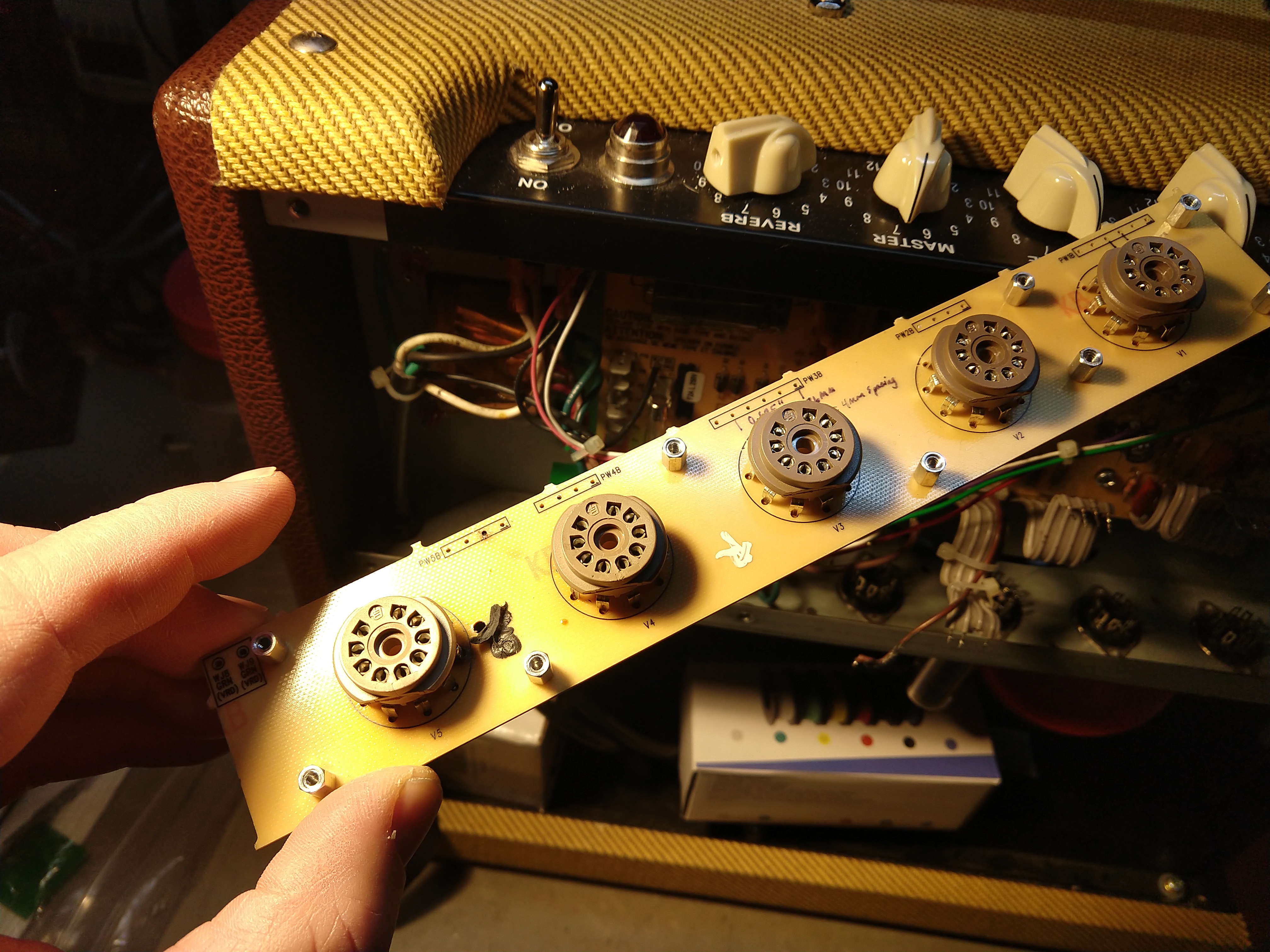
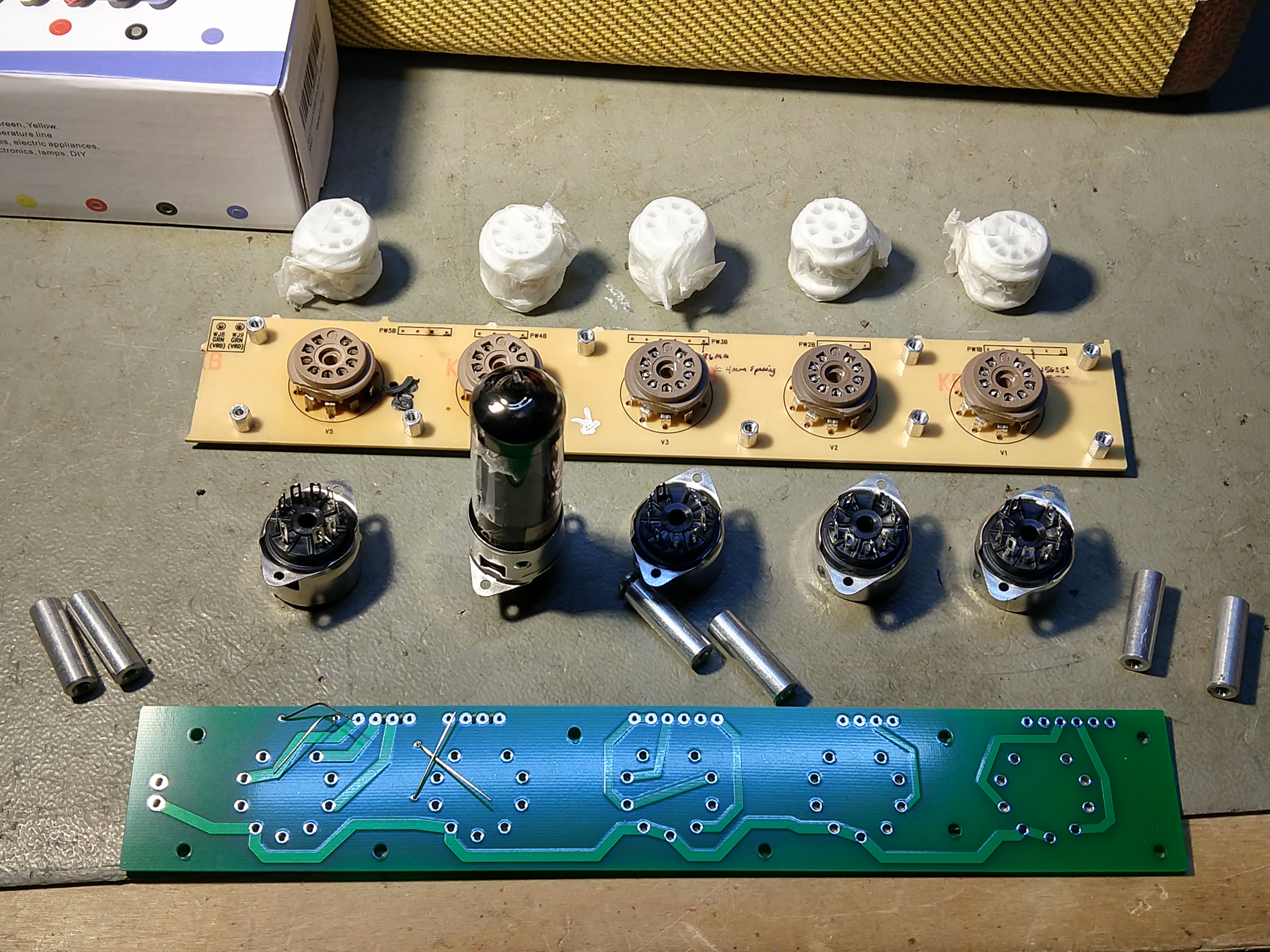
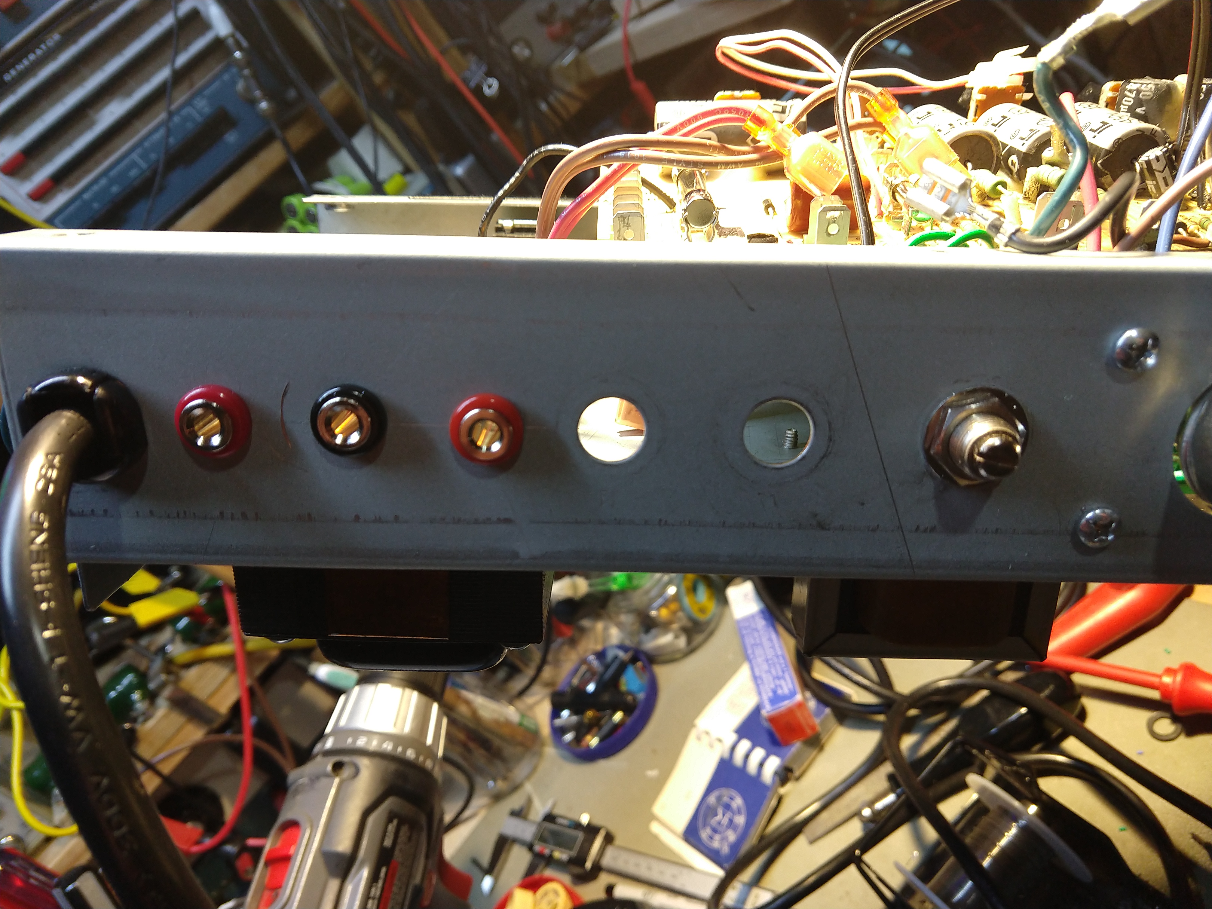
Making the hole locations for the new chassis-mounted sockets. I decided to “fly” the sockets to make durability even better. No more stress from tube movement to the solder joints.
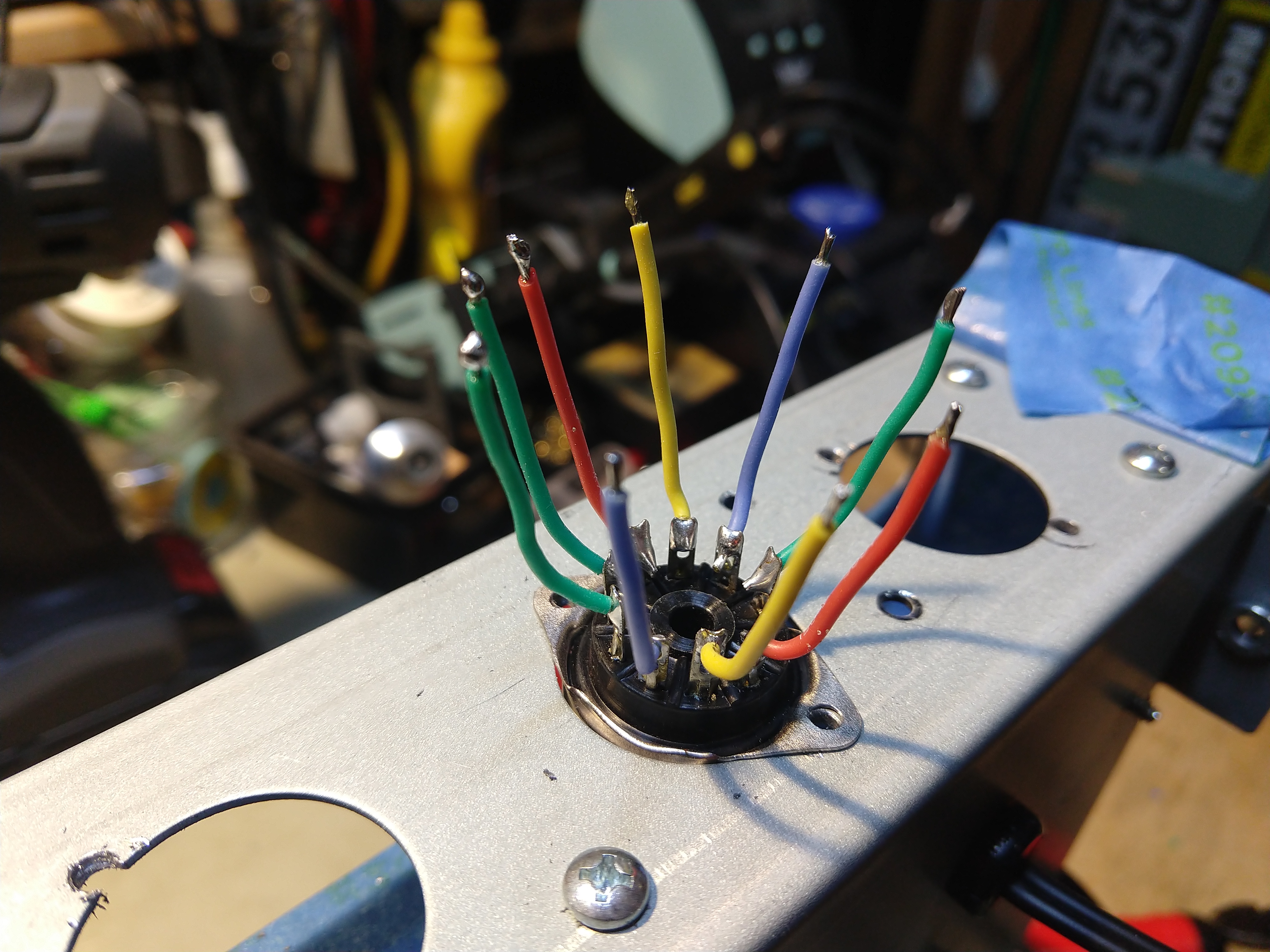
Note the socket mounting holes are on the hairy edge – the existing holes are a little oversize for standard chassis sockets, but you have to use small mounting screws to allow room for the mounting holes. Use washers and lockwashers as well so assure things stay in place. This is the kind of fiddly tedious build that is difficult to do in production, and so is avoided.
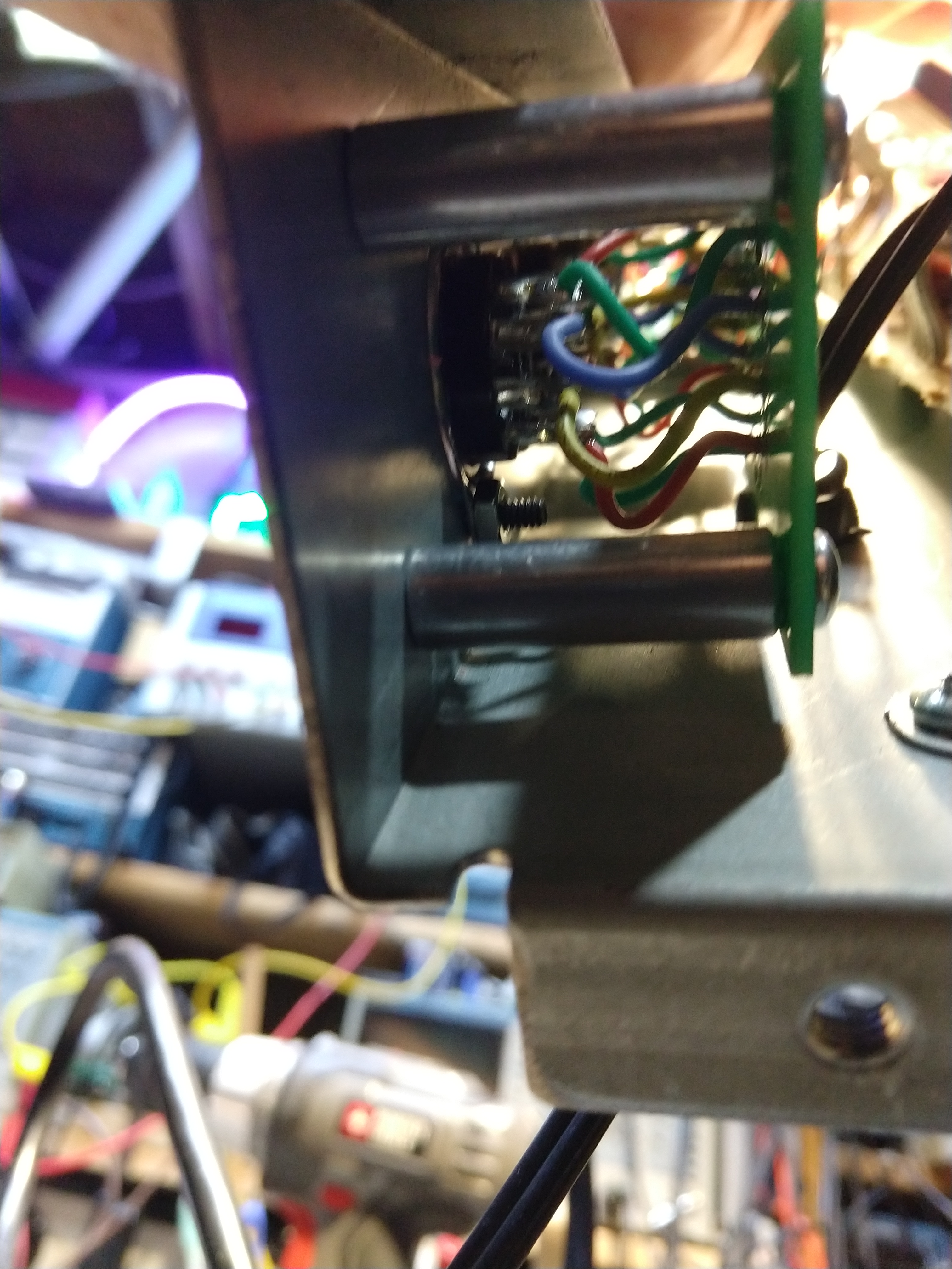
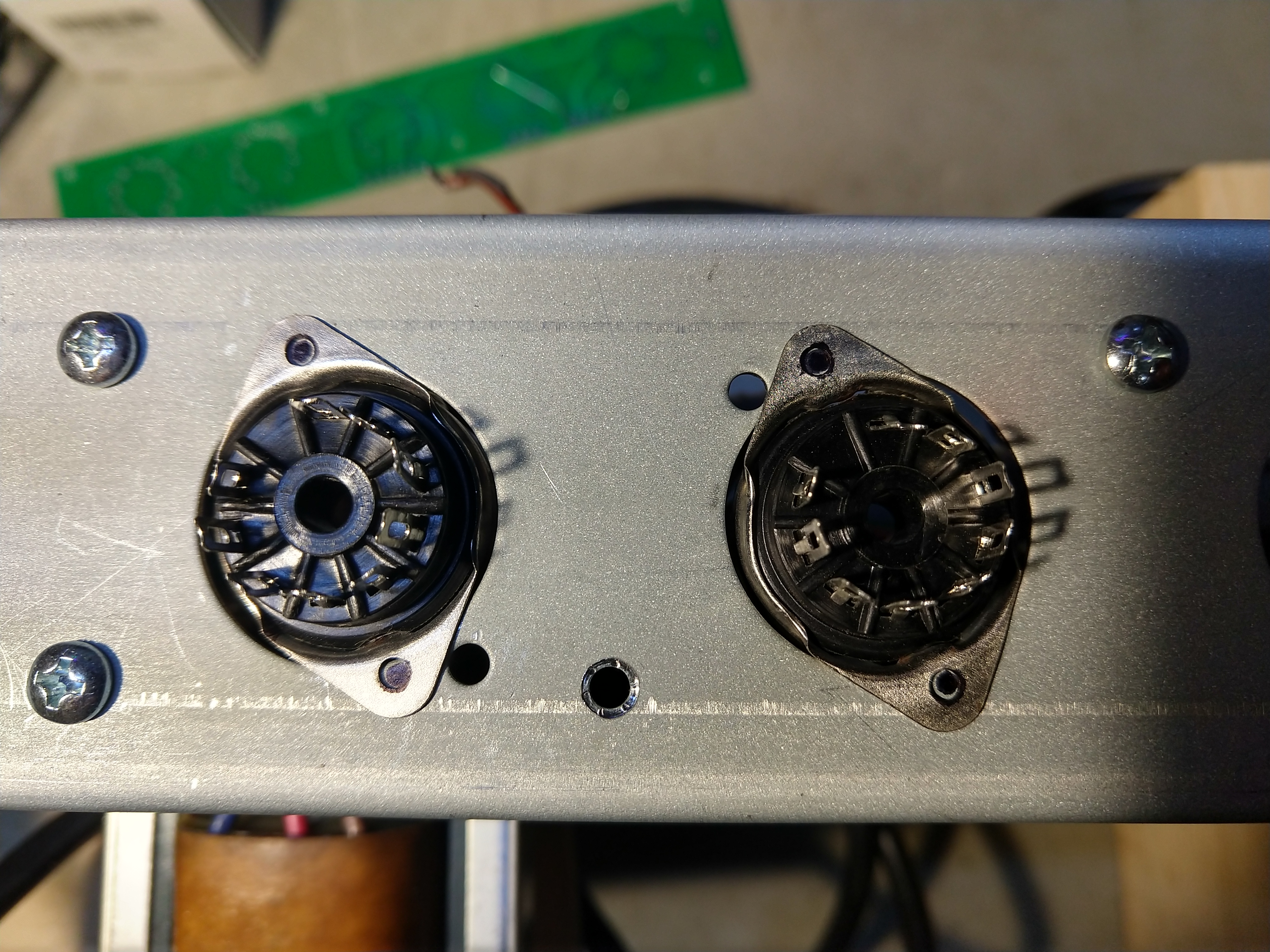
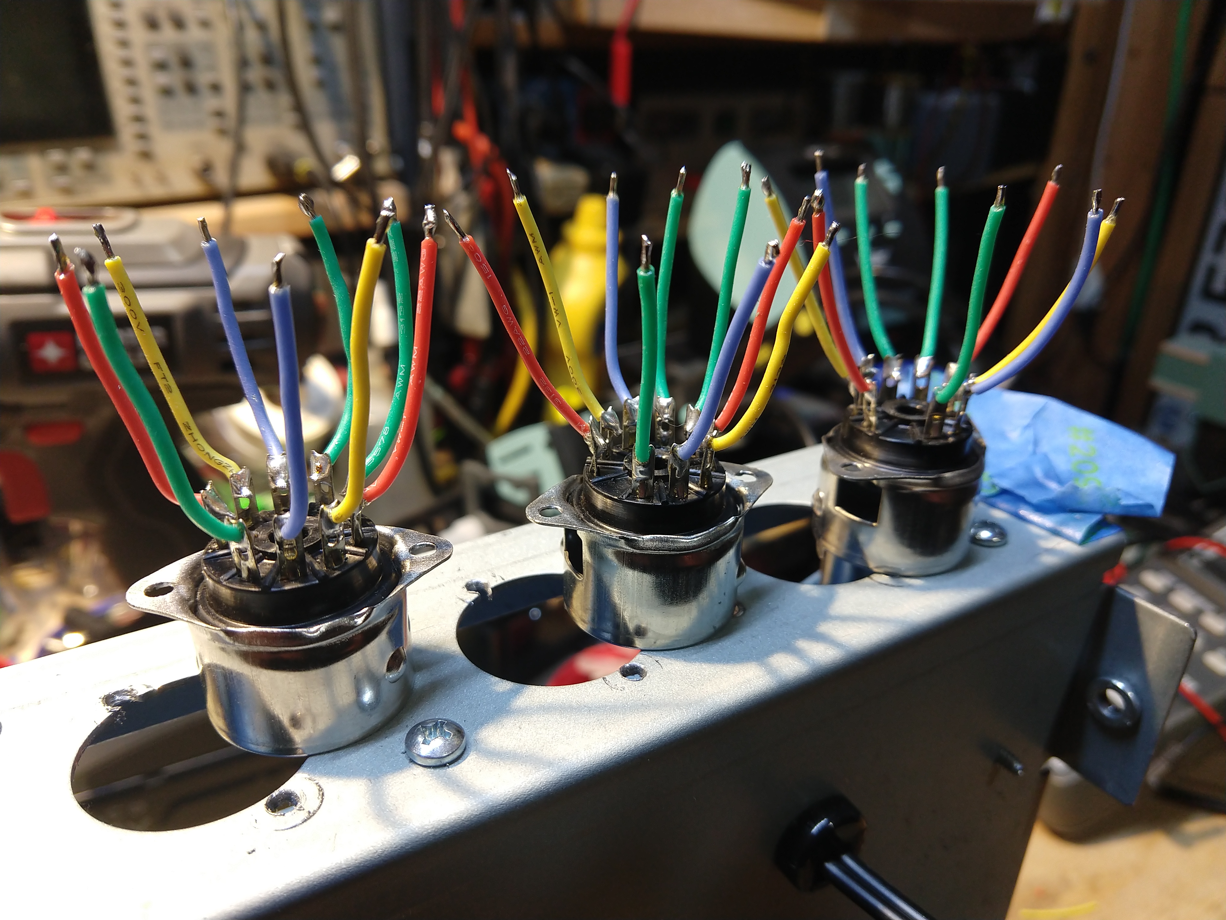
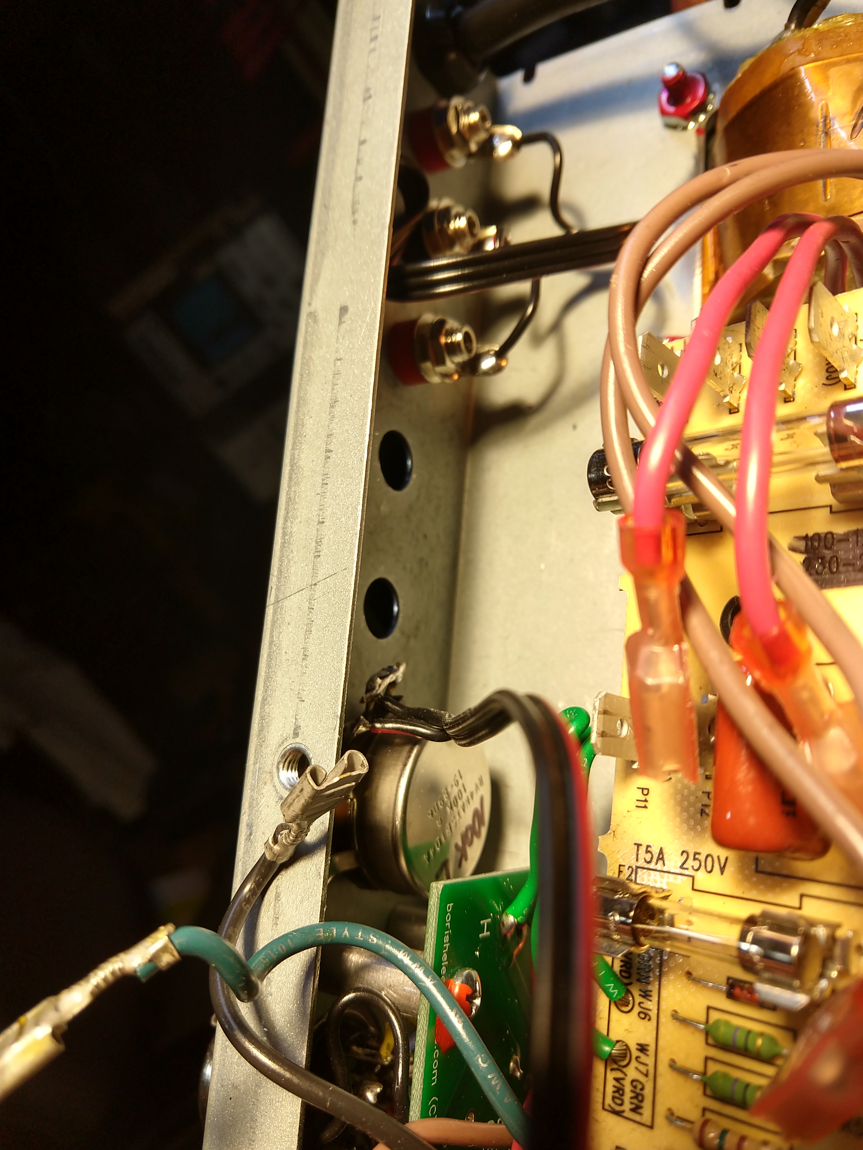
You can see the mounting hardware in this detail shot.
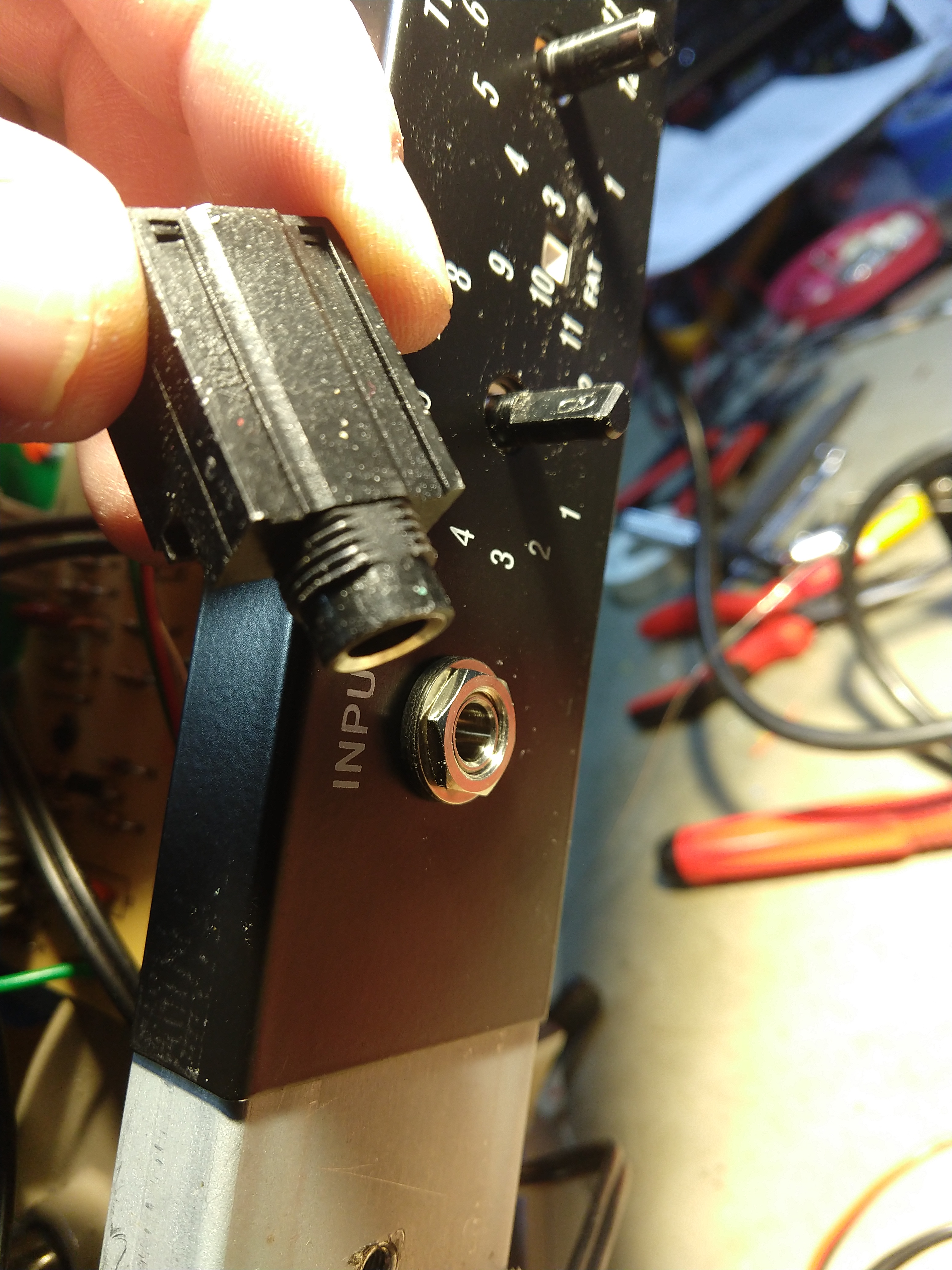
Ever take a 15-foot walk on a 10-foot cable? When you to, this plastic jack will deflect and bend enough to rip it free from the single-sided PCB. A solid metal Switchcraft with insulating shoulder washers is a better solution. Flying leads make the install easy and durable.
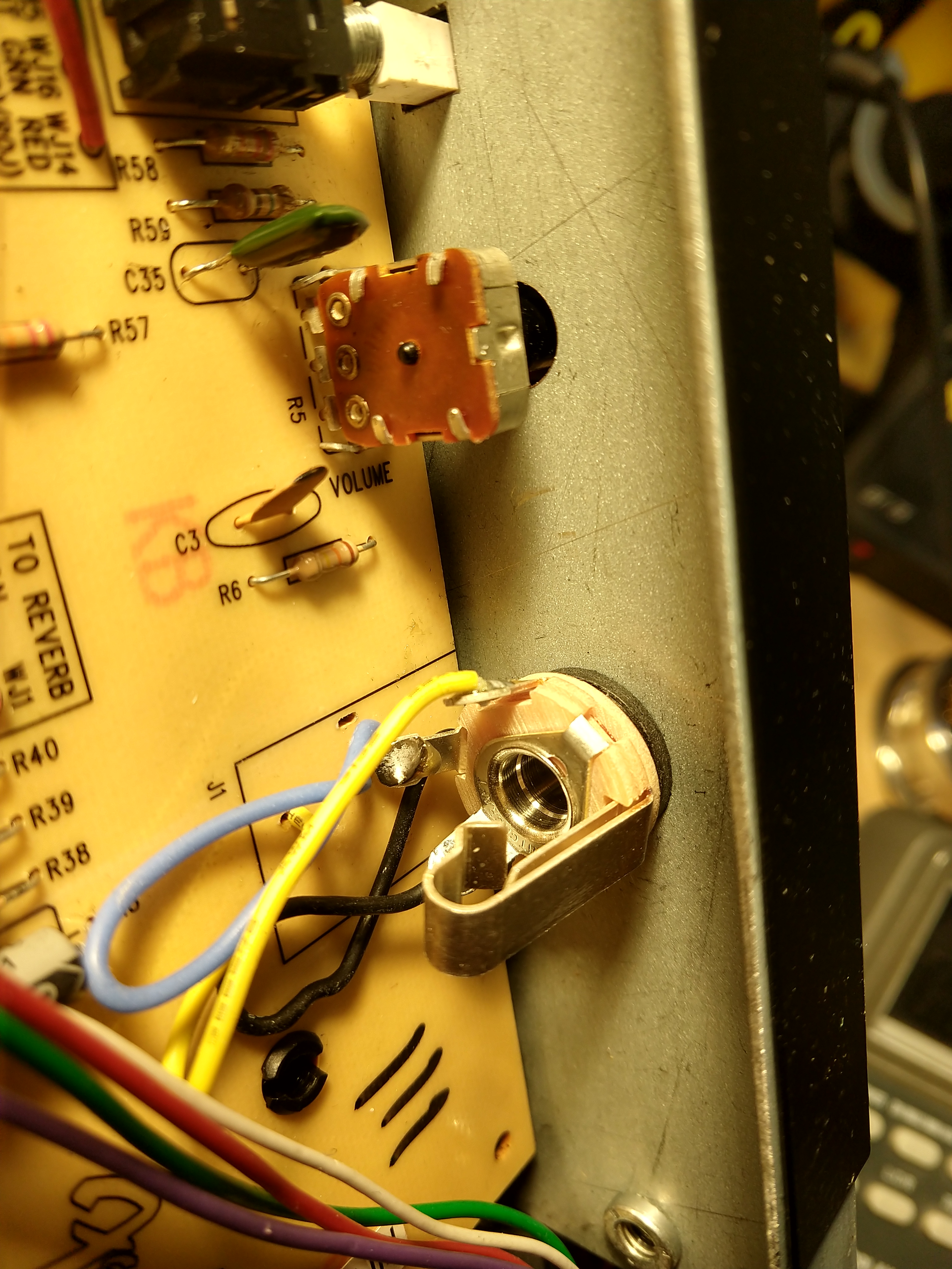
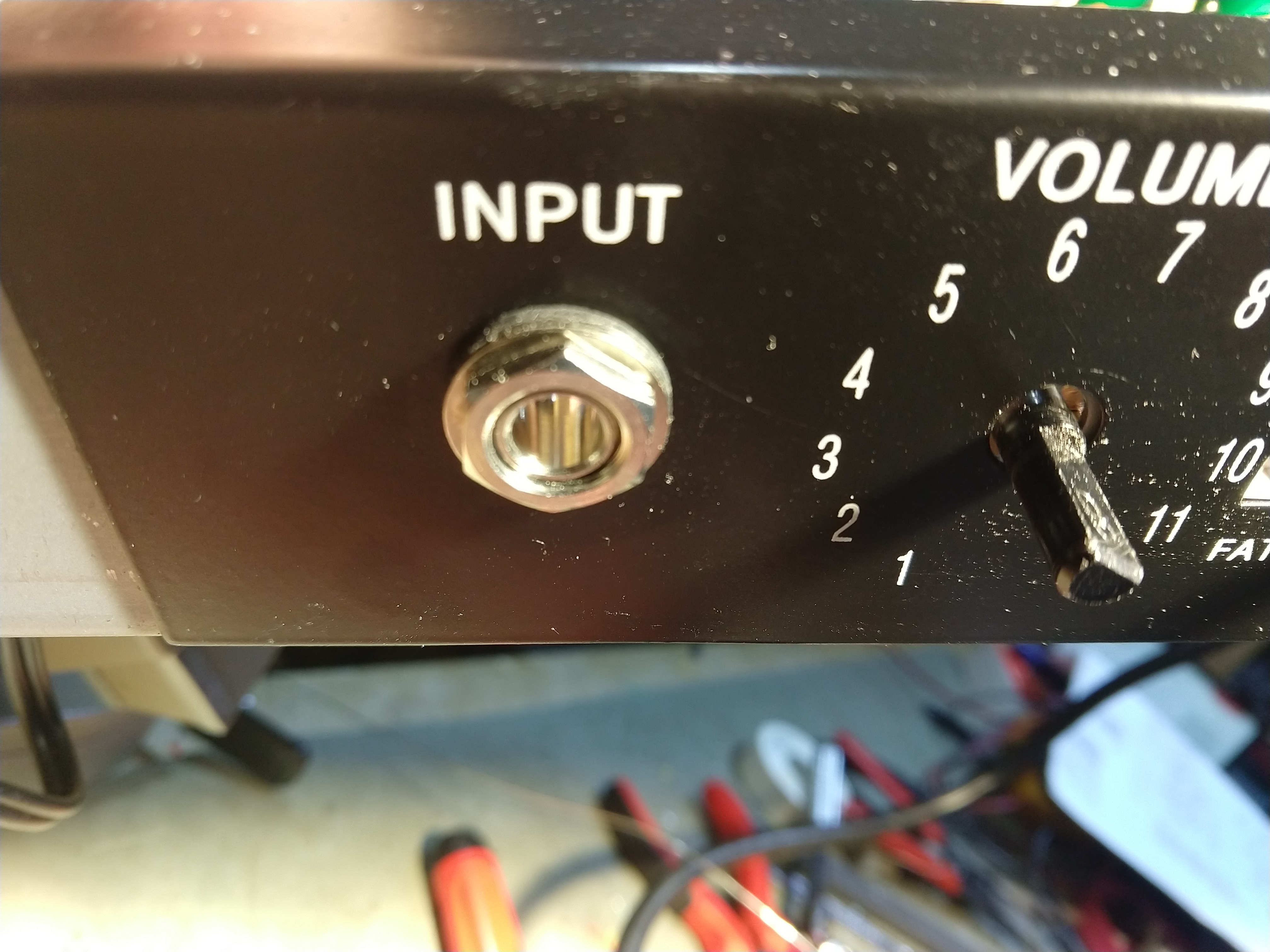
And it looks better too – that quality vintage vibe of an old Fender amp.
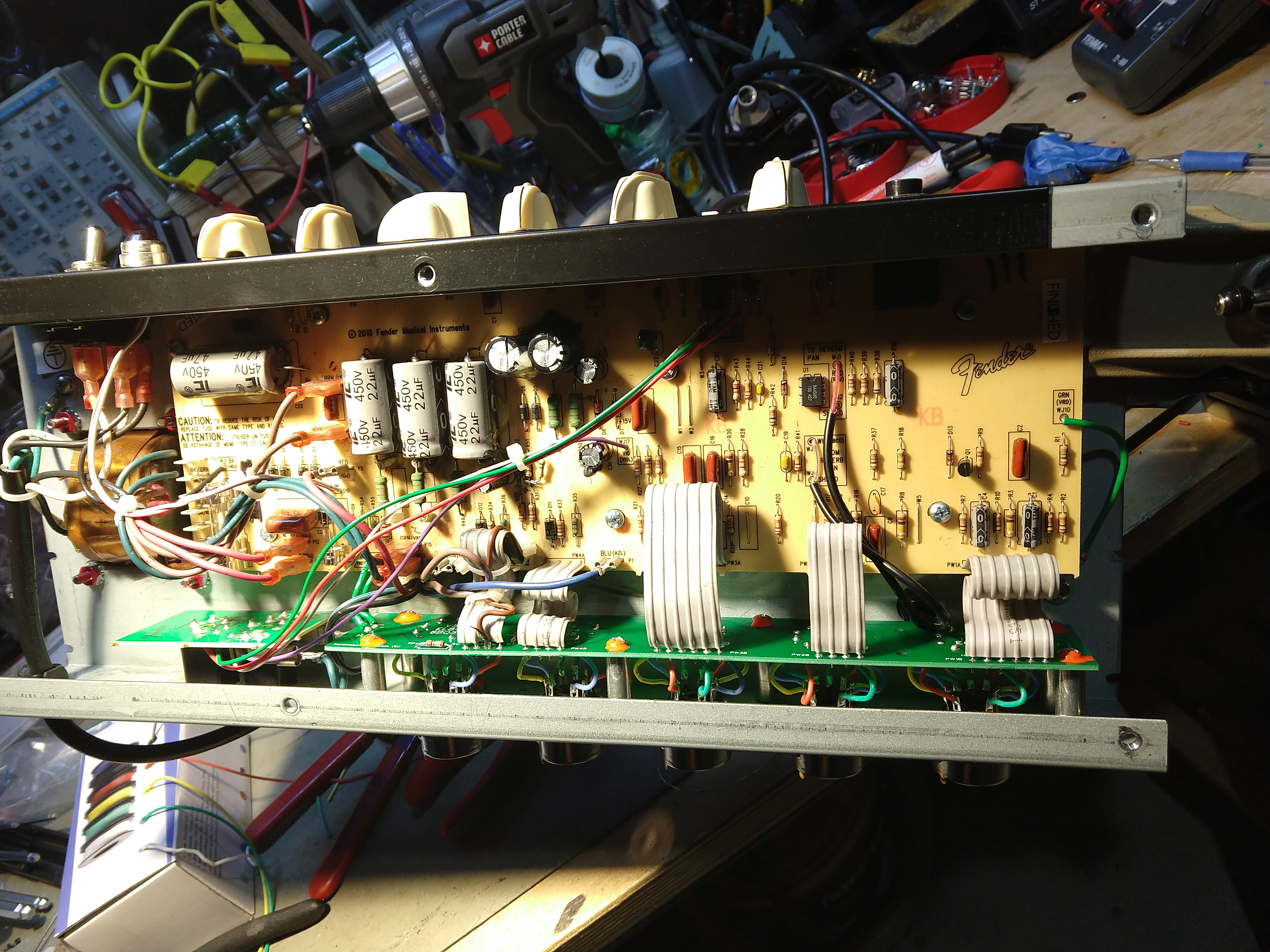
Bias current test point for each tube, a local ground reference and a new bias pot were added. This amp can now be biased without removing the chassis.
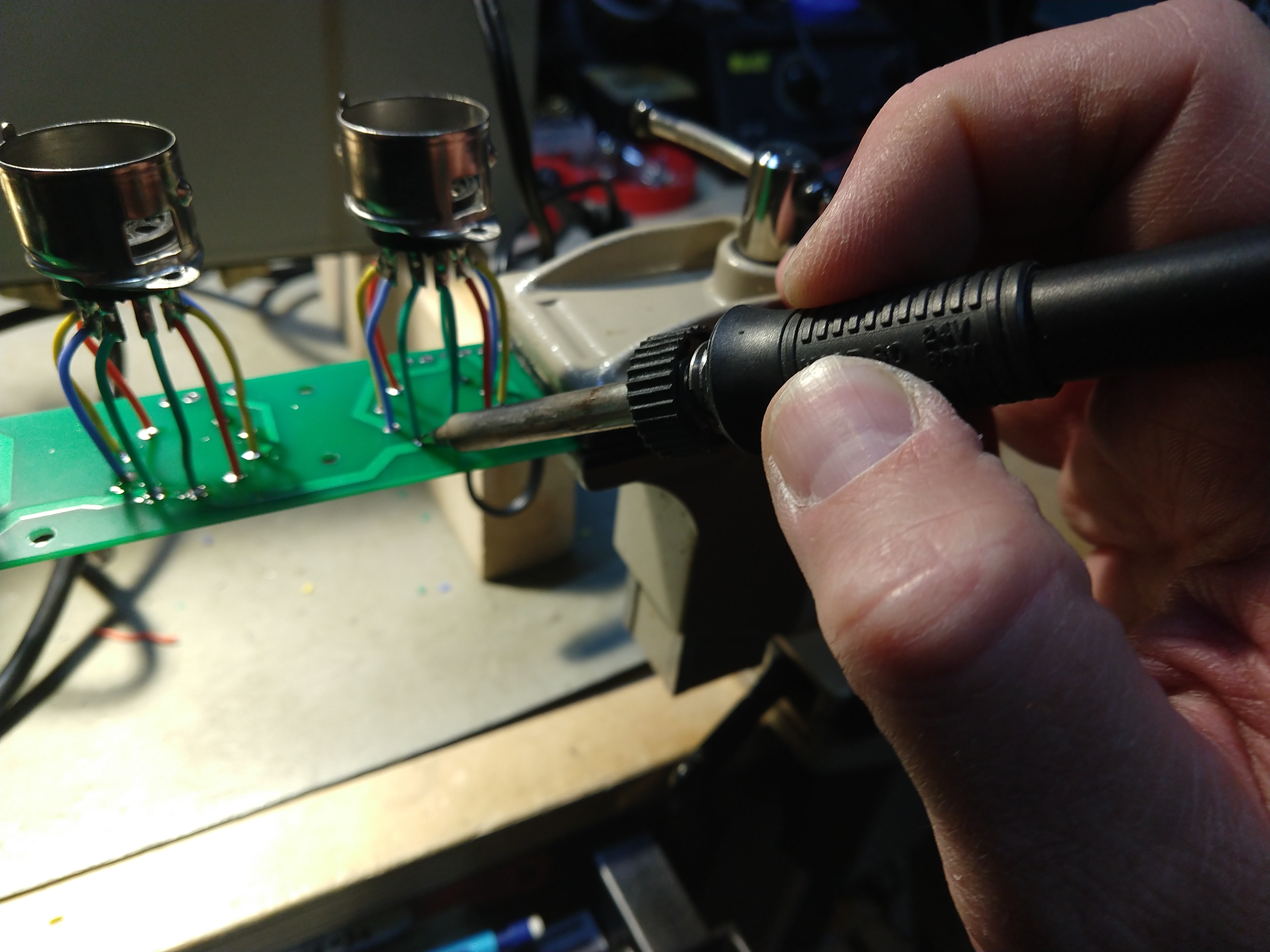
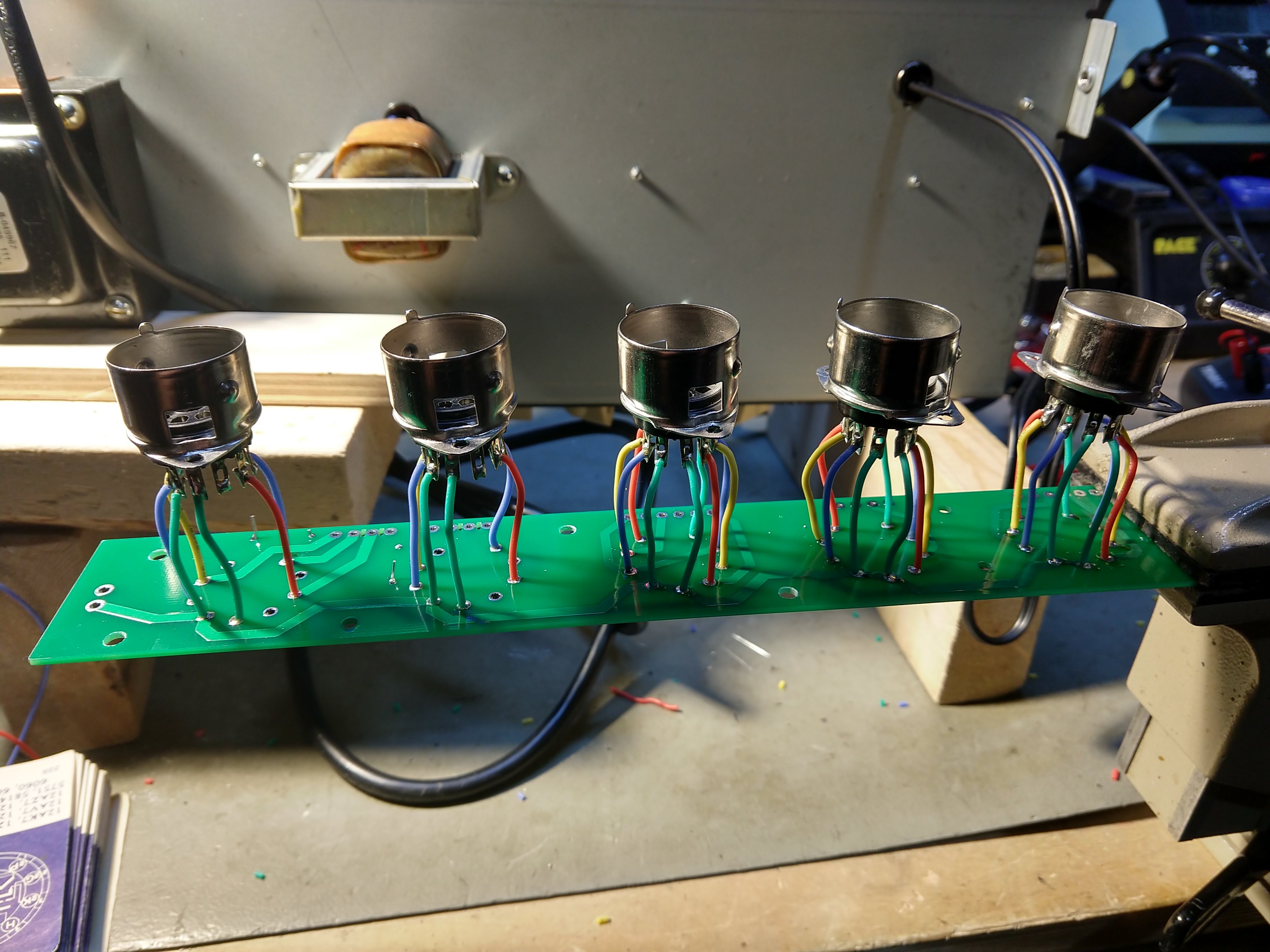
Final bench test before reassembly.
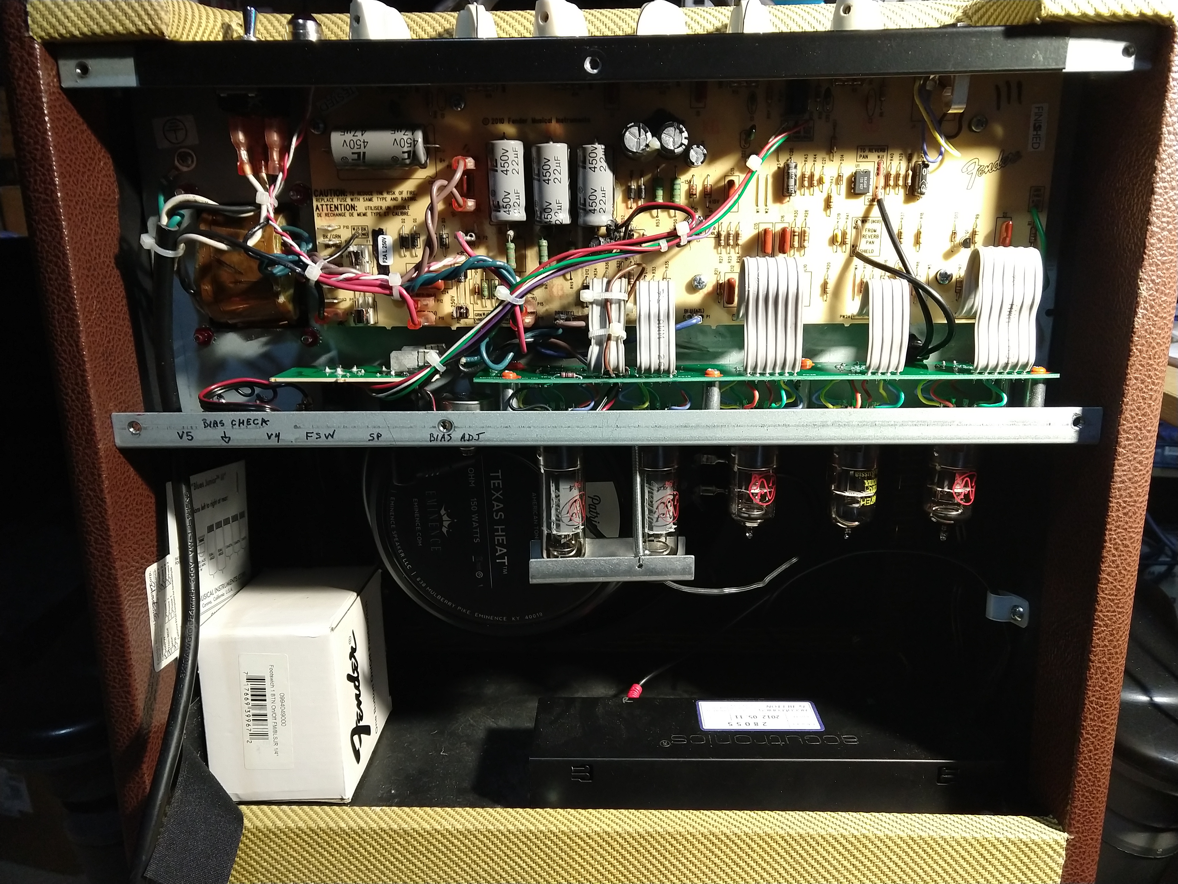
A bit of labeling to make sure it’s clear what’s been added.
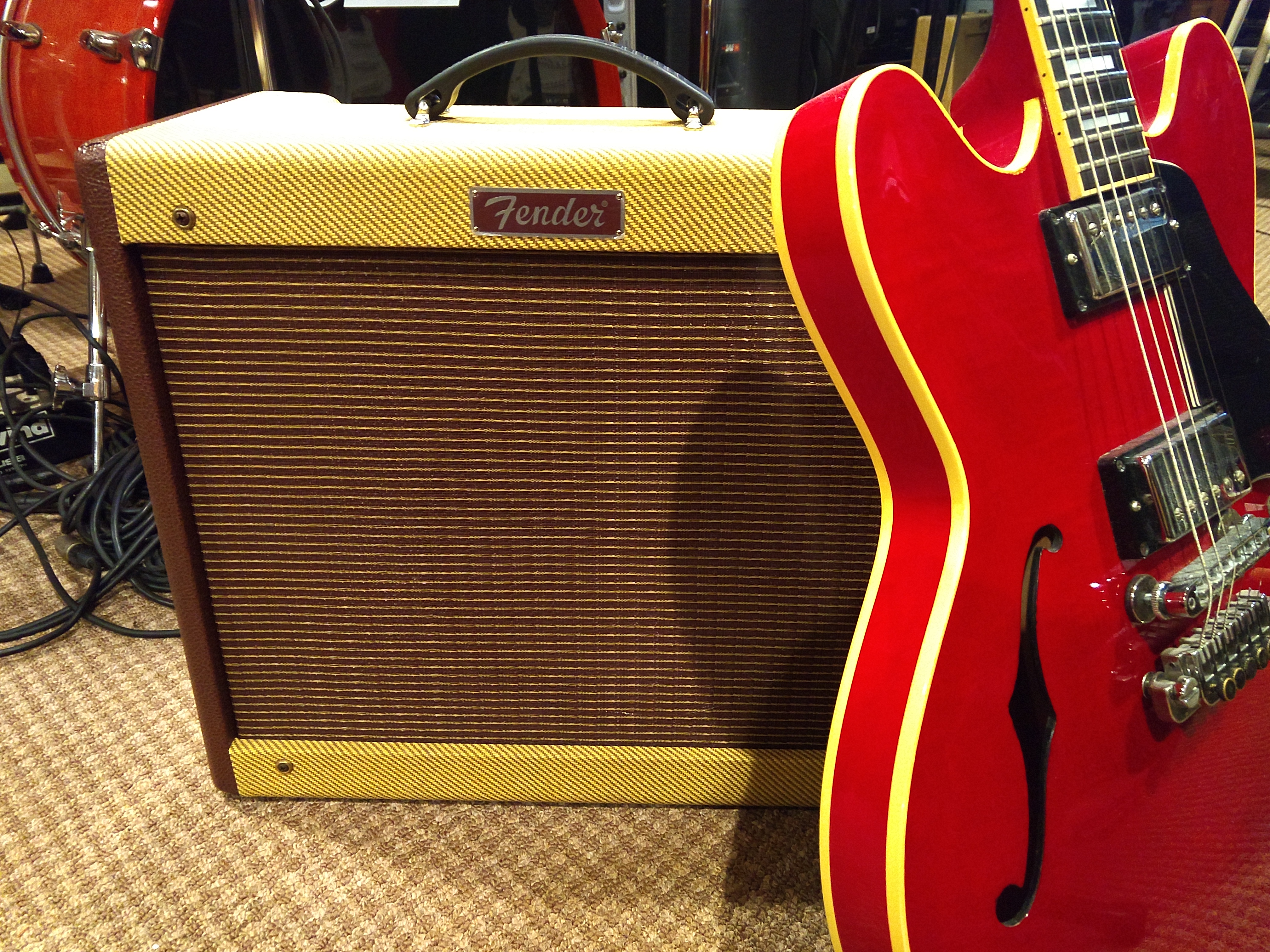
Ready to rock for the next couple of decades. Nice looking amp. Despite that, I sold it on, as I have enough Fenders and couldn’t justify holding on to it. I used the cash to help fund a new SQ-6 digital mixer for the studio.
