I recently made some progress in understanding how the series III Morris Minor fuel gauge system operates and how to calibrate the gauge. I thought I would bring my experience here where the world can find it and I can easily edit it as needed as the adventure unfolds. The idea is to present the theory of it all for all Minor owners to let them better keep these things running, and to update it with tribal knowledge from the Minor community as needed. That said, it’s originally an MS Word document, but I will try to post it here in a form that can be viewed locally. I’d like to avoid letting the document as it is out into the wild where I can no longer control it’s content or update it comprehensively as I learn more.
The Early Morris Minor 1000 Fuel Gauge System Calibration D. Brasier, MyTubeAudio LLC, 8/2024
So, after taking a couple of gold-speedo MM1 gauges apart, examining them with an eye loupe, desoldering everything, measuring each component with a good Fluke meter and putting it all back together, this is what I have found and how I understand the system to work. It may (or may not) be a good basis for how to test and calibrate these as it is based on an absurd sample size of just two gauges, so please keep that in mind. Updates possible, so comments are encouraged for the empowerment of the whole MM owner’s community by collecting and publishing our tribal knowledge. The research and photos here are original to me except for one stock photo courtesy of the East Sussex Minors website, for which credit is given.
My goal was to understand enough about these gauges to be able to accurately calibrate them. They are quite adjustable, however they are also easily thrown out of whack if you happen to loosen the wrong hex nuts on the rear side of them. This is apparently what the P.O. of my Morris had done at some point.
Let’s look at the components:
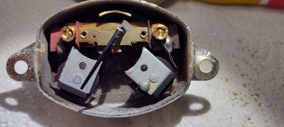
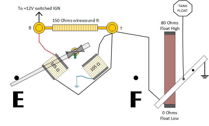
- 2 Coils, about 105 ohms DC each in resistance. The Full coil, right, appears a little larger in the diameter of its copper coil, but measures similar to the E Coil and both appear to use the same bobbin. (I did not measure pole-piece diameter, but they appear to be the same)
- 1 Wire wound resistor, about 150 ohms, bridging the B and T terminals
- 1 balanced armature with a resting bias weight (no springs!)
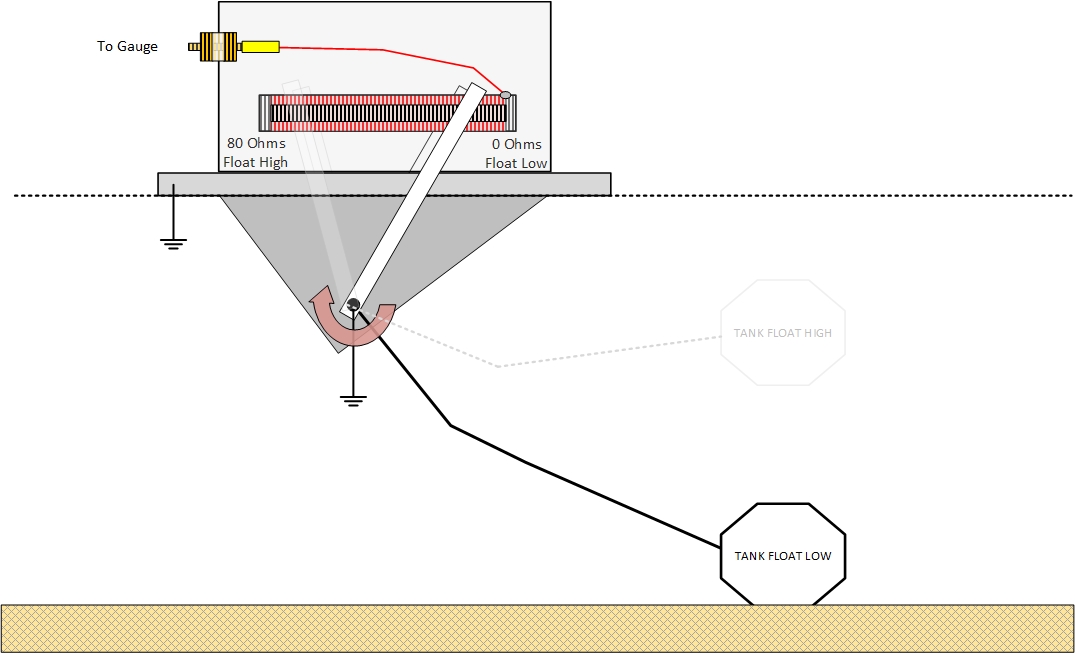
- 1 tank resistor, 0 to 80 ohms, of palladium resistance wire, and grounded out by a fork-contact that is connected to the float axis. This fork touches down on both sides of the resistor, giving some cheap redundancy against a broken single wiper. Here is a diagram of the important bits:

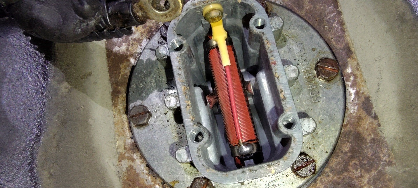
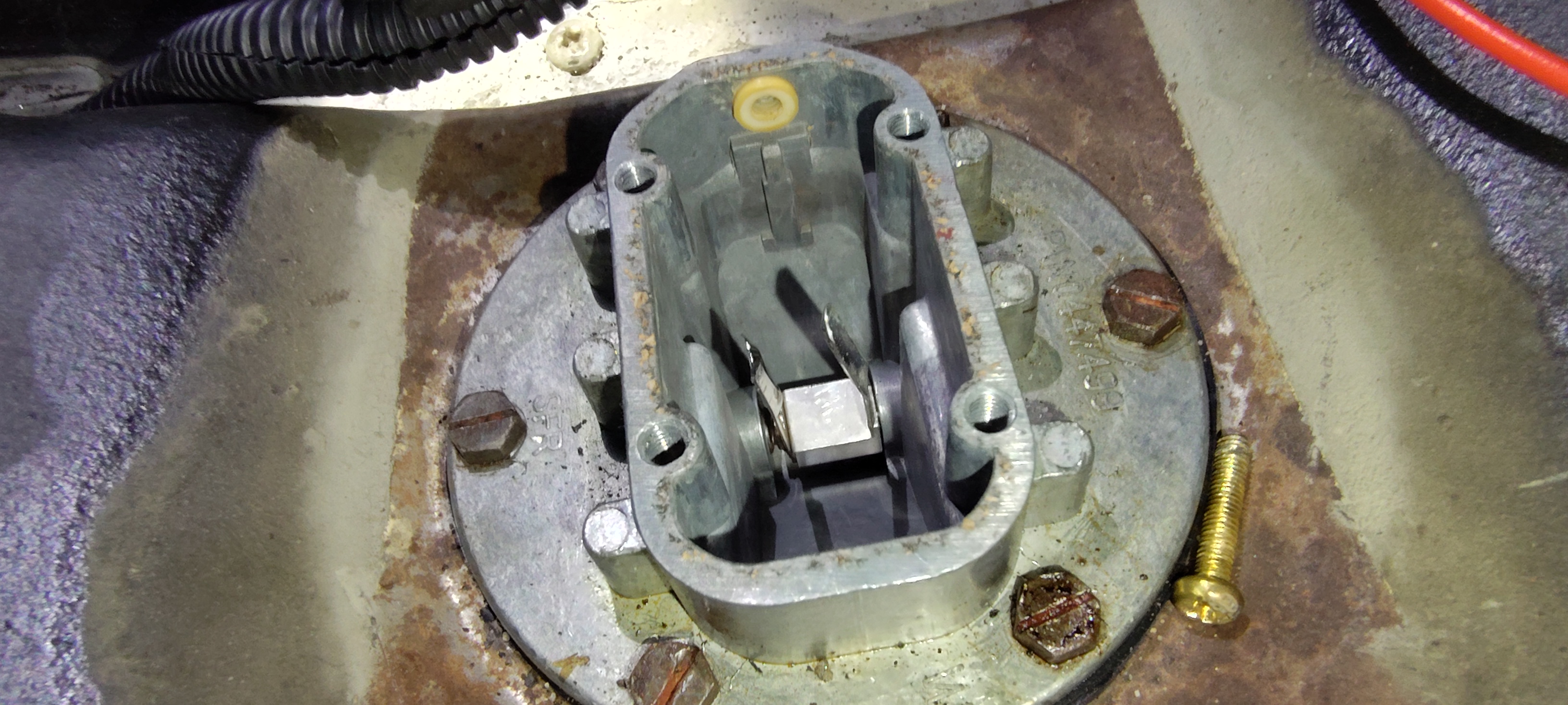
And likewise, a diagram of the sender:

And in real-life:

There are only three adjustments possible that I can see in this system:
1. The distance from the E coil to the balanced armature
2. The distance from the F coil to the balanced armature
3. The total angle of motion available to the float, which will depend on how much the float wire was bent at the time the sender was installed into the tank.
Because most of us do not want to pull the sender out of the tank, we have to be practical. What’s important is to know ahead of time that you are going to run out of fuel. Logically we need to know the real value of the tank resistor when that float hits the bottom of the tank. In my opinion, either draining it or running it dry are the best options, as it seems unlikely that an empty tank will every actually reach the zero point exactly. Meanwhile, I opened the sender up anyway to verify and measure everything inside.
While the fork-contact on the resistor can be finger pushed to the end-points of its travel, it seemed like a rather squishy point to find – it didn’t feel like it “hit the bottom”, or top, exactly at one repeatable point, perhaps because the fork itself is somewhat thin and flexible, or maybe the arm was deflecting a bit. I decided against this option. I will empty the tank later and measure the sender’s resistance, terminal to ground. That said, for the other extreme, I don’t really care how accurate the Full reading is, so long as it’s reasonably close.


This sender contains an 80-ohm resistor, and it appears to be linear, that is to say the middle of the resistor measures about 40 ohms. We can safely say any value between 70 and 80 ohms can be used to calibrate the Full setting. A couple of standard value 39-ohm 2- or 3- watt resistors in series will do nicely. Which end of the resistor is the Full end was determined by looking at external pictures of the sender and then considering what’s inside my own. The float appears to stand out and point away from the connection terminal (stands opposite of it), so that means when the float is raised, the fork is travelling up the resistor towards the terminal. (Caveat: It appears the arm could be reassembled to stick out either way if need be, so there is an assumption here that the ESM pic of the part is correct.)
But Mr. Lucas has a twist… the terminal internally connects to the resistor with a 1-1/2-inch long wire, at the FAR end of the resistor towards the float, NOT the end near the terminal. (See earlier pic) The terminal end of the resistor is left unconnected and free. This is not a voltage divider, just a variable resistor. Thus, a lowering the float rotates the fork towards the far-side, or wire-attachment point of the resistor (a.k.a., towards the rear of the vehicle) so it’s headed towards the 0-ohm end of the resistor as the tank empties.
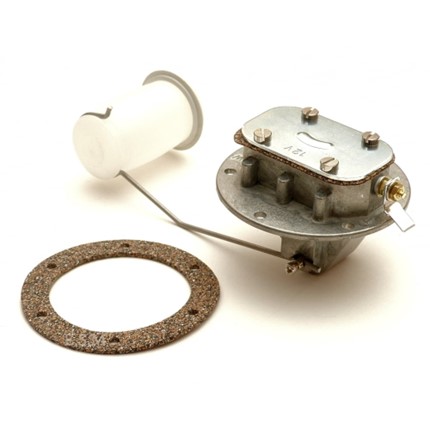
Photo source credit: ESM minors; https://www.morrisminorspares.com/fuel-system-c74/fuel-carburettor-c75/petrol-tank-sender-unit-float-pre-october-64-see-notes-p830603
And to refresh the eyes – another look at the cutaway of how it works (perspective from the other side view compared to above) :
Let’s look at the three cases I think matter.
1. Ignition off
2. Ignition on, full tank
3. Ignition on, empty tank
At ignition off, the meter movement is controlled by a small weight on the armature that wants to hang straight down, and should just about do so as the pointer hits the left dial-face nail. This keeps the needle below E and is the mechanical resting point with the key off.
This is a good time to point out that at ignition on, so long as there is any current flow AT ALL to ground via ANY setting of the float, (that is to say, any value between 0 and 80 ohms) there will be a voltage across the E coil. Look at the diagram. It will try to pull the armature towards it, even overcoming the little rectangular resting weight, which is seen in the diagram here in green. So the E coil is ALWAYS energized whenever the ignition is on. Keep that in mind.
In the next diagram, ignition is on, and the float is still at the empty point. That means the fork is towards the back of the car, towards the wire that connects to the output terminal, or put another way, towards zero ohms to its local ground, as there is now very little of the palladium resistance if any wire involved.
With zero ohms now across the sender’s terminal, BOTH wires of the Full coil (blue and black) are essentially grounded, so the Full coil does not have a voltage across it or any current through it to speak of, thus it does not produce any magnetism, and the standing field of the E coil is now the only game in town. The needle stays at E.
You will note in these diagrams that ONLY the F coil has one side tied to vehicle ground. At this point I will mention that I took my handy-dandy R. B. Annis magnetometer and verified there are no permanent magnets of any sort hiding in either of my gauges, in case anyone suspects their might be… I checked, and there simply isn’t.

Circling back to the vehicle ground point of the F coil, this is also why you MUST ground the gauge case to your given power supply if you are testing these out of the car or in the car with the speedo handing loose from the wires in the dash but not bolted in. The gauge body MUST have a proper ground *. Big caveat here – the F Coil (and only the F coil) gets its ground from its own Pole Piece mounting stud. That stud is also the calibration adjustment. This means that if your F-coil calibration nut is loose, or there is corrosion around the area that the cal nut tightens down on, you will not get the full intended current in the F coil and your calibration will be off. This is an important point.
Let’s now look at the case of a Full tank. In this situation, the rotation of the float has pushed the fork-contacts along the resistor body back towards the sender’s single terminal, which you will remember is AWAY from where the terminal’s wire is soldered to the resistor. This puts most if not all of the resistance wire into the circuit, adding more resistance in series with the big 150 ohm fixed resistor across the B and T terminals. In doing this we are now moving the T terminal electrically away from ground and letting a voltage develop across the tank resistor. That voltage at T is applied to the F coil (remember the other side of the F coil is already tied to vehicle ground) which creates a current through it, turning it into an electromagnet. It is the job of the F coil to overcome the static “always there” E coil’s magnetic pull and draw the armature over towards the F coil. As the sender’s forked contact moves towards the 80 ohm end of the resistor, more and more current flows through the F coil, pulling the armature and its indicating needle further and further towards it as it wins the magnetic tug-o-war.
*If you wish, you can alternately solder a small grounding wire to the F coil top plate near where the factory solders the fine magnet wire, but be careful not to break that fine wire as you do. I did not find this necessary

The calibration is then pretty straightforward once all of this is clear in your mind. If you know the “real” empty resistance of your tank sender, you just substitute that resistor value in between the T terminal and the gauge’s ground instead of connecting a sender. That real value, whether your car happens to be 3, 10 or 17 ohms, is all you need to have in place before you apply 13.8 volts to the B terminal. The only way to know this for sure is to measure it with an empty tank. Once you have a similar resistor value (** plus a few extra ohms to allow a reserve) connected from T to ground, you can ready your fingers for some serious fiddling, loosening and tightening the hex nuts attached to the coils and sliding them back and forth until the low-resistance E reading is accurate. Once that is close, you have to change out your low-value resistor and replace it with 70-80 ohms and adjust the coil positions so that the gauge reads somewhere near Full. You will do this many times to find the sweet spot. I used an alligator clip to quickly swap between the two resistors connected to the power supply ground.
There are 2 caveats to this cal process to keep in mind:
1. loosening the Full coil nut WILL remove it’s ground each time, killing your reading, so you have to re-tighten, check it, loosen it, move it a tad more, tighten, re-check, etc., many times until you get it right.
2. The E coil can be left a little loose so many small E cal adjustments can be made during each single F coil position trial, until the two forces balance out perfectly for your car’s E (low, measured) resistance vs. the 70-80 ohms you are using to cal the Full coil with. These forces are balanced in opposition, so they are touchy and interactive, and with the nut/grounding issue of the F coil playing into it, it just takes some patience to find the right balance.
– Dan Brasier, MyTubeAudio LLC, Holland, MI, USA, 8/23/2024
**I think the E point should be calibrated several ohms above the measured sender value with an empty tank, and here’s why: It will allow you a little reserve fuel left after the gauge needle hits E. Everyone wants that, or?
